How hard could it be? They’re just pieces of plastic… Near the beginning of the pandemic I was considering fixing the gaps between my teeth, and began researching how I might do it myself mostly for the sake of the technical challenge. I found Amos Dudley’s blog post, and investigated the possibility of replicating the steps with consumer-grade equipment.
Summary: All of the fabrication steps except for creating the 3D scan are feasible with inexpensive equipment. My attempt at photogrammetry is close but not quite sufficient to replace the 3D laser scan without some tedious error correction. Determining the sequence of 3D models that serve as the forms for the aligners is, of course, a matter of orthodontic expertise and not the intention of this report.
Disclaimer: I am not an orthodontist. This is a description of fabrication processes, not a guide for orthodontics. I am not suggesting that you do this. I do not benefit in any way from you reading this: I am not posting any affiliate links, my own monetized videos, etc. I will not do this for you. My specific case was very simple and I have no reason to believe that others’ are similar.
Background: After wire braces, I had a Hawley retainer that broke easily. I eventually stopped getting it replaced, and thought of getting plastic orthodontic aligners to fix the drift that had occurred since then. At the beginning of the pandemic, I was wary of what would have been a relatively high-exposure process, and was interested in the technical challenge of replicating it. I found Amos Dudley’s blog post, and I would not have been able to figure this out without that as a guide. This is mostly building on his work and documentation. He had access to professional-grade machines through his university, and I wanted to see if it was possible with consumer-grade equipment. I don’t know of anyone else has done something similar. I am not claiming priority. I wanted to see how inexpensively this could be done. The cost of the replacement for the Hawley retainer was comparable to the cost of this entire project – and those retainers exert less control over the teeth than full trays.
Contents
- Alginate Impression of the teeth
- Plaster Cast of the Impression
- 3D Scan of the Plaster Cast: Laser Scan
- Series of 3D models made for the treatment
- 3D printing of each model in the series
- Duplication of the 3D prints to plaster casts
- Vacuforming plastic sheets over the plaster casts to make the aligners
- Post-processing of the vacuformed plastic sheets
- 3D Scan using Photogrammetry
Taking the impression
This video describes the process well. I first bought plastic trays for this, but then I made my own because my mouth did not match the shapes provided. I considered using the 3D printer to make trays to do this, but was worried about excess resin, and it was faster to prototype and modify the tray made out of cardboard that was suited exactly to my mouth instead of printing or buying more. I covered the cardboard with packing tape for waterproofing. Dental impressions taken by dentists and orthodontists were poorly suited to the shape of my mouth in the same way that the bought plastic trays were, and the process was much more pleasant when self-administered with a custom tray.
I used a plastic cup for mixing the alginate powder with water and a plastic knife in place of the putty knife applicator. It took a few tries before I was able to reliably get a clean impression.
Pouring the mold
I used a plastic cup for mixing the plaster with water and a plastic fork for whisking. Tapping the tray with the poured plaster was sufficient for removing bubbles.
The 3D Scan
A digital model of the teeth is created from a 3D scan and then manipulated to create the sequence of models in the treatment. The scan needs to be accurate within the maximum step size so that the unmodified model is less than one step away from the teeth as they are. Then the second step may modify the teeth once they are in agreement with the 3D model of the first step. I did not have access to a professional 3D scanner, but I was able to pay someone with access to a NextEngine scanner to get what I could consider the ground truth further scanning attempts. Description of the attempt to replace the laser scan with photogrammetry makes more sense after understanding the remainder of the steps, so will come last.
Creating the Treatment Series
I will not comment on the core orthodontics of this because I am not an orthodontist. I will describe this from an engineering perspective because that is how I approached it.
Outside the domain knowledge of orthodontics, what can I deduce about how the orthodontic process works? What is the input information, and what is the output? The output is a series of 3D models of the maxilla or mandibula. If attachments are used, the algorithm should also produce those positions. The input information should be: an evaluation of dental health from visual inspection and dental records about past procedures, a 3D scan of the teeth, and an X-ray scan. The X-ray scan provides information about the positions of the roots of the teeth.
Suppose the teeth are perfectly rigid bodies, the mandibular and maxillary bones are rigid, and the connections between the two are like springs. The plastic aligners are semi-rigid bodies. When the arrangement of the teeth in the model differs from that of the real teeth, the model’s corresponding aligner produces a force on the teeth on the opposite side of the direction of movement. By Newton’s 3rd law, to produce such a force on a single tooth (suppose in the simplest case just a single tooth is targeted for movement) there must be an equal and opposite force distributed over other teeth. After being placed over the teeth, the aligner deforms and the teeth move such that the sum of the force vectors is zero. Critically, the deformation of the aligner (or of wire braces) cannot be ignored, and the resultant position of the teeth is not necessarily the same as the corresponding 3D model for that step.
Are there any restrictions on the movement possible? The aligner pushes against the teeth on the side opposite the direction of movement. For movement along the axis of each tooth (root to tip) there are not surfaces available in both directions, barring some concavity or irregularity on the surface of the tooth. The purpose of “attachments” is to make such surfaces available for axial movement.
So the aligner exerts forces on the target tooth and some of the other teeth such that the force vectors are balanced. The magnitude of these individual force vectors should be proportional to the difference between the real position of the teeth and the 3D model. What happens next? If I didn’t know anything about the physiology of the teeth, I would assume there is some adjustment in the connection between the teeth and the jaw that happens after every step. It turns out that the periodontic ligament is just that ‘spring’ connection, and that the bone surrounding the tooth will undergo harmless dissolution if a light force is applied against it, necrosis if a heavy force is applied, and the bone on the opposite side will grow to fill the cavity left. The goal is to exert a light force consistently to avoid this necrosis. Below some force magnitude, the surrounding bone will not undergo meaningful reshaping, which is why the opposite force vectors on the non-target teeth do not permanently move them. To apply this light force, the displacement of the teeth should be within some bounds. I have found values for this myself, but of course this is not something for which I am a proper source.
As anyone who has had orthodontic treatment knows, you can feel the magnitude of the force on your teeth. But don’t feel it ‘on’ the teeth themselves because there are no nerve endings on the exterior of the teeth. You only feel it in the living tissue inside of them and the ligament that connects them to the maxillary or mandibular bone. The physical sensation is a source of validation for the proper fabrication of the aligner. I can report for myself that the magnitudes of the forces applied in this sequence that I designed myself were much smaller than the feeling of the wire braces. When I had wire braces, it physically hurt to eat for a day after each adjustment, where here it was completely painless. For safety, I set the step size smaller than what I had found in the literature. It took longer and required more steps in the sequence, but the physical discomfort in the process was less and I could be (more) confident in the health of the process. With wire braces, if they are manually adjusted, you are simply putting your trust in the dexterity of the orthodontist to move them the correct amount, but with 3D printed positives, you have literal CNC control of the movement. I believe there are also automated wire bending tools now, so I’m not sure if this is a strictly superior method at least in this respect. I can’t speak to the relative accuracy and precision of such tools relative to the print and double-transfer process that I describe here.
I will refrain from going into the details of how exactly to determine the sequence for such a treatment. The thought of building a physics model to estimate the displacement of the teeth given some state and aligner shape crossed my mind, but I judged it to be unnecessary. My case was extremely simple, and I only learned what was necessary for it specifically. I’ll just say that it is more sophisticated than linear interpolation.
I did also have access to the X-ray scans of my mouth. Knowing about the physical positions of the roots of the teeth helps to determine the force system that the periodontic ligament exerts at any displaced position and the requisite change to the aligners. However, I don’t know if in name-brand treatments the X-ray scans are integrated with the 3D scans of the impressions of the teeth to compute the orthodontic sequence. I would think they would be very helpful, but I’m not sure. For the “teleorthodontic” treatments in which the client takes the impressions themselves, they of course do not have access to an X-ray scanner, so those treatment options go without integration of that information. In typical practice the orthodontist may simply use the X-ray scans for the evaluation of dental health. I did not do any sensor fusion either. I just used the scans as a reference to evaluate their health, estimate the spring force system, and be more confident that they would not collide with the movement I was planning,
Moving the teeth in Blender
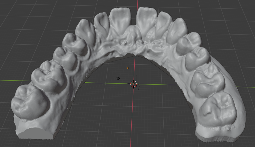
Blender is free open-source software used for 3D modeling. It has a variety of uses in this project. When doing photogrammetry, it can be used to clean up the 3D scans. The major use is moving the teeth through the sequence of positions that are the sources for the 3D prints. To do this, I isolated the points of the mesh for each tooth that I wanted to move. Then, I manually determined each step and moved them at each iteration within the appropriate displacement value and within some boundary for angular change (again, it is more complicated than this).
Further benefits of a DIY treatment sequence
I had complete closed-loop control over the process. I was able to print as many steps of the sequence as I desired instead of printing the entire set and then doing a “readjustment” or realignment after a long series. If I made a mistake in any step, I could throw it out at negligible cost.
3D Printing
Preparing the Models for printing
- Verify that the dimensions of the scan are correct by using the Measure tool in Blender.
- Make a cut in the rear of the model so that there is an affordance for easily removing the print from the print bed.
- Add an embossed number to each print for easy identification of each step in the sequence. Because the step sizes are so small, you may need to use calipers to distinguish them.
- A print raft is not necessary because we don’t care about the bottom of the print.
Note the cut in the top left corner. This will make removing the print from the build plate much easier.
Printing
I bought an Elegoo Mars stereolithography (SLA, Resin-based) printer for this project. I had used fused-filament fabrication (FFF, extrusion-based) printers before, but the required resolution for this project would not have been possible with a consumer-grade printer. SLA printers are almost perfectly suited for this use case because they have impressive resolution (50 microns) and print in layers, which is aligned with the form factor of the prints (wide with low height). There are many great resources on Youtube for learning about 3D printing, and you could start with this video from 3D Print Farm.
Removing the print from the plate
I have not seen the following recommendations anywhere else. This process makes printing in batches much easier. In order to remove the print from the build plate without having to re-level the build plate after each print (which requires cleaning it to not risk any resin getting on the screen through the paper that is used for leveling) you should remove each print with these steps, which are somewhat specific to the Elegoo Mars printer:
- Unscrew the large knob that holds the build plate fixture to the arm.
- With the gloved non-dominant hand, grab the build plate by putting the thumb on one side and the other fingers on the opposite side across the narrow direction of the build plate.
- Hold the build plate over a small container that will be used for rinsing the print.
- With the included pallet knife in the dominant hand, insert the pallet knife in the notch in the print and twist the knife about the lengthwise axis (like turning a door knob). This creates a lever arm on the edge of the knife while having good control. Trying to use the pallet knife as a wedge by pushing in to the notch or turning it up does not work as well because the pallet knife is more flexible along that width-wise axis.
- The print then drops into the cleaning container.
- Return the build fixture to the build arm, and retighten the knob.
This means that at no point did you exert a force on the build plate and the knob segment at the same time, so their alignment hasn’t changed, and you don’t need to re-do the alignment of the build plate. I had first printed them without a notch, which made them difficult to remove because there was no affordance. I also tried to use the pallet knife as a wedge while the fixture was lying on the table, which changed the alignment of the build plate with the knob segment.
This allows for printing the steps in a sequence, cleaning them all together, and cleaning the printer once instead of for each print. Each of these prints took about 1hr 15min, so over the course of a day you can easily print 6+ of these. I found the process of cleaning the resin off of all the components tedious enough that consolidating the cleaning was very valuable.
Safety
It is important to understand that the resin is an irritant and you need to take the appropriate precautions when handling it. You need a well-ventilated room or garage. You need to follow the relevant rules for disposal of the uncured resin, especially for the cleaning supplies, because it is considered a hazardous material in its uncured form. There is more maintenance and cleaning required than an extrusion-based printer.
The reason that the resin printer is appropriate for this use case despite the additional required precautions is the resolution that it offers. In my experience, there is less adjustment and more confidence that the print will come out correctly on a resin printer than an extrusion printer. My one failed print happened when I pushed the build plate fixture out of alignment between prints without re-leveling it. Otherwise, the printing worked every time.
Cleaning
Some put emphasis on the cleaning solution for the resin print. I found that the most effective means of dislodging uncured resin was to directly brush the print with a tooth brush while it was in the cleaning solution. I did not see a difference in the results between the Mean Green Degreaser and Simple Green cleaning solution. Others use a hypersonic cleaning chamber. I did not find it to be necessary.
Curing the prints
In addition to cleaning the prints from remaining liquid resin, to ensure that the resin is fully cured, UV curing chambers are also used. I made my own from LED light strips of the appropriate wavelength in a box in which the interior sides were covered with aluminum foil and then the strips were overlaid. This gave a much larger volume than the of-the-shelf curing chambers I found, which allowed me to process them as a batch.
Duplication of the 3D prints to plaster casts
For the sake of safety, I chose to duplicate via double-transfer the 3D prints to plaster casts before vacuforming. First, I wanted to make sure that there would be no uncured resin transferred from the 3D print to the plastic aligner. Second, I did not know the thermal properties of the resin print. The plastic while doing vacuforming is made very hot, and I did not know if that had any chance of melting the print which would contaminate the plastic shell. To do this double-transfer, I made 3 jigs out of cardboard and packing tape in which I could do the alginate mold plus plastic cast. This was fairly straightforward. I was worried about a loss of precision and possible introduction of inaccuracy from each of these transformations, but this turned out not to be an issue.
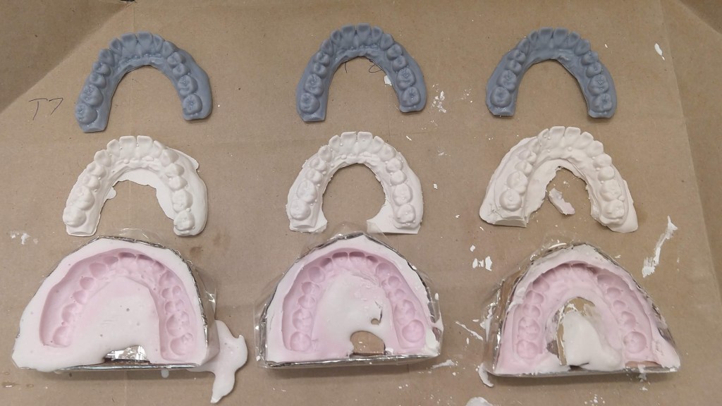
The other reason why this may have been necessary (even if it turned out that there was no safety concern) was that it may have been too difficult to remove the vacuform from the 3D print, whereas with the plaster cast it can be destroyed in the process. I never successfully removed the vacuform from plaster cast without destroying the cast.
Vacuforming
To create the actual plastic aligner, we can heat a certain kind of plastic so that it becomes flexible, place it over the object around which it should be formed, and apply suction through the table on which the object is placed to suck out the air, which forms the plastic around the object. The casts around which we want to do the vacuform are small enough that the suction provided by a household vacuum cleaner is sufficient. To make the table, I made a box with holes drilled in one side and an opening for the vacuum cleaner hose in another. The region with holes was matched to the size of the plastic sheets that would be formed. To make the hole for the hose, I first traced the hose opening, cut out the same shape in cardboard, and then surrounded the hole with duct tape so that there would be a flexible seal around the hose as it was inserted. The other five faces of the box I made from MDF, which gave it rigidity.
For the heat source, I used a toaster oven that I got for this specific purpose instead of the kitchen oven as a precaution against any contamination of the kitchen oven with released fumes or particles. Also, the toaster oven was portable.
Then there needs to be a rigid frame to hold the plastic sheet while it is heated. I made a frame out of scrap aluminum by cutting four ~1″ x 6″ strips, making an incision on both narrow sides, and then making a bunny-ears wrap joint between each of the four strips to make a square. The key is that this frame should be thin so that there is not any unnecessary gap to the table, which could worsen draping effects. I then used eight “book darts” to hold the plastic sheet to the aluminum frame. Paper clips could also be used. Or, make one similar to a picture frame as shown in this video.
I then made stands attached to the toaster’s rack by taking aluminum foil, folding it over several times, and then shaping the strips into triangles with roughly the same height.
Vacuforming steps: Place the plaster cast on to the table, remove the plastic film if there is one from the plastic sheet, secure to the metal frame, insert the frame to the oven, heat the oven to ~325 deg F, wait until the plastic bends, turn on the vacuum, and then with thick gloves take the frame and lower it evenly onto the table. Wait for the plastic to cool so that it solidifies, turn off the vacuum. Detach plastic sheet from metal frame.
It might be possible to remove the the aligner from the plaster cast with just an x-acto knife, but it was easier to start with a small pair of scissors. Then remove burrs from the edge with the x-acto knife. Other sources call for a dremel with a special deburring tool, but I was able to get a clean edge with just an x-acto knife. Finally, wash the aligner thoroughly.
Professional-grade machines to do this are strangely expensive when it is just a heating element, vacuum source, table with holes, and tray. I suppose you can charge relatively high prices when your customers are high-margin businesses.
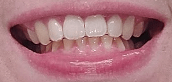
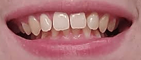
Wearing and Results
I took 3 weeks for each step, wearing the aligner except when eating. The obvious benefit of DIY (stated again) is that you can discard it and start over with low marginal cost if the magnitude of the change feels too large. I never had to do this, however. There may be some risk that wearing an aligner on only one set of teeth could affect the other set. I did not observe this.
Before:
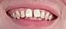
After With Aligner:
After Without Aligner:
Photogrammetry
Photogrammetry is the process of obtaining physical measurements from photographs. Here I used a specific application of it: the creation of 3D models from a set of 2D images. My goal was to determine if I could get a 3D model of my teeth accurate enough to use as the basis for an orthodontic series. After reading the description of the entire fabrication process, you now have the context for the requirements of photogrammetry. Keep in mind that the 3D models will be printed and then their duplicates will be used as the positives for vacuforming. If a tooth is smaller in the model than the actual, the aligner will not fit over it. If it is larger, it will make exerting forces on it more difficult. If it is translated or rotated, the aligner will exert unexpected forces on the tooth.
As described above, I got the plaster cast of my teeth scanned using a NextEngine 3D laser scanner. This is a professional-grade machine, and it gave very impressive results. Orthodontists either take a scan from a plaster cast using a similar device, or from within the mouth itself with a specialized camera.
I had known about photogrammetry before this project, but this was my first attempt to use it. I had also considered building my own laser scanner or integrating a projector to do a structured light scan, but that would further increase the materials cost, and require very precise calibration to get right. With some searching I found these resources from Holocreators and Peter Falkingham on Small Object Photogrammetry, and decided to pursue photogrammetry with just my phone camera.
Similar to Peter Falkingham’s guide, I made a light box from a cardboard box, white LED light strips, and copy paper. I used a tripod to have my phone in a steady position relative to the box and a remote clicker so that I wouldn’t need to disturb the phone by touching it, which would cause blur.
From there, I used the open source Meshroom/AliceVision software to process the set of images into a 3D model. This requires an NVIDIA GPU. If you don’t have one you could use the Google Colab free tier to process the images. This notebook provides an example.
The mesh output from Meshroom can be cleaned up and examined in Blender. Note that you will need to scale the output from Meshroom by taking real measurements on the cast and then scaling the model such that the distance for the measurement of the equivalent points is the same.
Because the plaster cast is uniformly white, it does not offer good visual features for the automated extraction of keypoints by the photogrammetry software. Here it helps to have some understanding of the underlying process. The first step is to extract visual keypoints which, loosely speaking, are visually striking and distinct points on an object that should be apparent at different angles and distances, and when collected together can be used to identify an object and the angle at which it is observed. These are things like edges, corners, regions of high-frequency color changes, etc. Once these visual features are extracted from every image, their positions within each image can be compared to determine the camera position and angle that corresponds to each image. In turn, this allows for finer estimation of the distance from each camera angle to every pixel in its image. Read more at AliceVision’s guide.
The unmodified plaster cast has relatively few such keypoints, and to add more, I painted the cast using acrylic paints to create a high density of color changes and edges. I had first tried just using pencil, pens, and markers, but painting in small strokes and dabs with partially blended colors on the brush offered much better visual feature density. This was a very low cost modification to the physical object which greatly improved the scanning performance. Laser or structured light scanners operate on a similar principle of creating visual features, but instead project some pattern or point onto the object and then record the resulting deformation of the projection to make measurements.
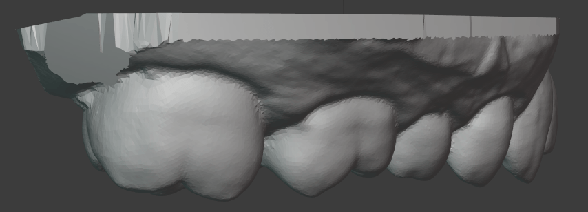
The result of the photogrammetry was accurate to the laser scan within ~0.6 mm almost everywhere, which was impressive for just a phone camera and open source software, but not quite good enough for unmodified use as the basis for an orthodontic sequence. There is certainly much more that I could have tried. Perhaps I could have gotten better results by experimenting with the Meshroom settings.
I manually configured the camera focus and exposure time to get high resolution and contrast. The automatic setting of the other features seemed to be good enough. One problem I encountered that may be somewhat specific to this use case was that it was difficult to get a consistent level of focus on both halves of the teeth. The photogrammetry examples I have seen have been on objects that are mostly convex. Here I attempted to take close-up photos with high resolution in which the ratio of distances between the camera and the different parts of the object was significant.
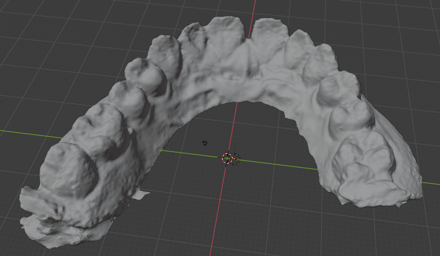
Note that the left rear molar is missing because I used an incomplete fragment for my photogrammetry testing. The above image shows the raw result. It could be cleaned up in Blender with smoothing, refining some of the edges, etc.
My result was not even in the same class as Peter Falkingham’s for what I assume are objects of similar size, but he also had a DSLR camera.
To compare the photogrammetry result with the laser scan I used CloudCompare. See these tutorials:
Cloud Compare – aligning and merging meshes
Cloud Compare – Change Detection
My results:
Despite the insufficient accuracy, I think it would still be possible to use only the photogrammetry techniques described so far if you use a somewhat tedious error correcting process. After validating that it looks correct visually (no major defects or deformations) and checking with the measurement tool in Blender, you can do a few things:
- Print it, do the vacuum forming, cut it out, and try to fit the plastic shell over the original cast. The shell is somewhat flexible, so it should be possible to fit it over the cast if it is close, and you can hopefully observe the areas where the fit is not correct, and then make adjustments in Blender. Obviously, the better the scan, the fewer adjustments need to be made. Flexibility means that it should be possible to fit it over the shell despite concavities.
- Because the cast is rigid and your teeth actually move slightly, it may be more difficult to fit the shell over the cast than over your teeth. Given that the goal is to eventually fit it over your teeth, you can just try to put the shell over your teeth and then literally feel the regions where the fit is not right. If it can’t actually fit, you need major adjustments, and then you can feel if there needs to be a move and in what direction from the force on your gums. Of course, it is important to not try to force it. Again, I have not tried to do this.
Doing the corrections would take some skill in Blender.
The goal for the variance of the scan should be less than the recommended step size. A scan within that variance would be equivalent to one step size which should be just barely perceptible. Instead of starting with the first “treatment” tray, start with the product of the unmodified scan so that there is agreement between the scan’s starting place and the sequence of the treatment.
I also was aware of newer neural network-based approaches to constructing 3D models such as Neural Radiance Fields but the convergence times for these were quite long. Iteration speed was important in trying to construct the photo set and analyzing how to improve it, so I decided to go with the more established tools for this investigation. I expect that within a few years these newer approaches will become more efficient and mature for this use case.
The photogrammetry process is quite tedious compared to the cost of having it done with a laser scanner. If you would enjoy learning this skill, go for it, otherwise, it is probably simpler to find someone with access to a scanner (perhaps a university student or someone in a maker space) who could do this for you. Unless you want to track your progress very precisely, you would only need a single scan. This is the only part of the process for which consumer-grade equipment is not sufficient.
Conclusion
Overall, this project was more like acquiring a time-intensive hobby that eventually saved money than what one might think of as a DIY solution. Again, this is not orthodontic advice. I am not encouraging you to do this. My case was extremely simple.
Bill of Materials
The total cost when I purchased these materials was about $430. Availability or cost may have changed since then. Of the purchased materials, the cost of durable goods was about $310 (mostly the 3D printer), and the unit cost of consumables was approximately $60. I paid $100 to have the laser scan done.
- Materials Purchased
- Dental Impression
- 3D Printing
- Elegoo Mars 3D Printer
- Elegoo Resin, 1000g
- LED Light Strips, 400 nm
- Paint Filters
- Microfiber Cleaning Cloth
- Simple Green cleaning solution, ~$10
- Vacuforming
- Plastic Sheets for Dental Vacuforming Use
- Toaster Oven, $40
- Photogrammetry
- Materials Already Available
- 3D Printing
- Funnel: Placing the paint filter in a funnel when pouring the unused resin back into the container gave it a rigid structure and was more secure.
- Vacuforming
- Vacuum cleaner
- Frame
- Scrap Aluminum Sheet
- Book Darts
- 3D Printing
