
Eucharistic processions bring the presence of Christ to the public. We want to have them regardless of weather, but most procession canopies are not made of fabric suitable for use if raining. What is the right form of a weatherproof canopy for Eucharistic processions? It should look liturgical and indicate the meaning of the procession. For it to be used even in rain, it should be waterproof. It also needs to be lightweight, rugged, and disassemblable for transportation. The dimensions should accommodate a priest holding the monstrance.
First, here is a typical canopy design (read more about them here).

Second, here is our weatherproof design. In place of the typical ornate style, we chose to use a simple set of symbols (Chi-Rho, Alpha-Omega) which are some of the oldest Christian symbols, to visually communicate the meaning of the procession at a distance. Other visual or graphical styles are possible within the weatherproof form.

In this post, we describe the design, fabrication, and usage instructions of the canopy so that it can be used as a basis for future work. These canopies successfully shielded the priest from rain in processions and withstood collision with many branches on urban streets and sidewalks.
Design
We chose a triangular prism or “tent” style so that rain would flow off the sides. There are three major components of the canopy: the frame (interior structure), the cover, and the poles.
Major Dimensions and Materials
The frame is 53.5″ wide, 71.5” long, and 24” tall. The poles are 7’ long and 1.75” in diameter. The length of the cover is 72” to give some tolerance for fitting it over the frame. The cover extends past the bottom of the frame by about 14.5” on each of the four sides.
The poles are 7’ long in total. Based on availability of wooden dowels at the requested 1.75” diameter, I chose to use 4’ and 3’ poles combined with a dowel screw. The color and exterior pattern of the wood was not consistent between the dowels, so I tried to match the color of the 3’ and 4’ members of each pole from the set I ordered. The dowels could have been painted or stained for better visual consistency. I considered adding finials at the ends of the poles but couldn’t find suitable ones within the timeline for the project.
The poles are connected to the frame by an eye screw on each side and a double-sided clip. The clip was about 3” long. The clip allows the poles to move with some freedom relative to the frame, which helps in not requiring the bearers to be in perfect synchronization as they walk.
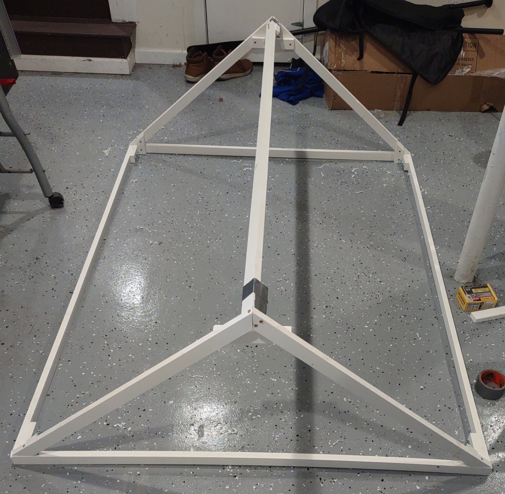
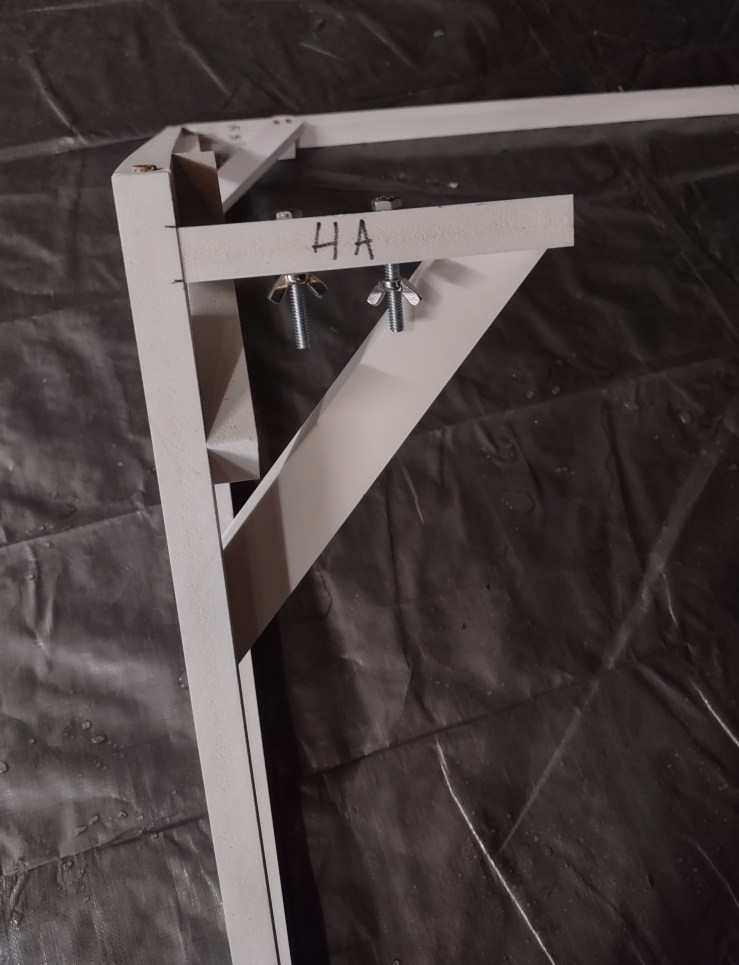
The frame consists of two triangles at the front and back and three length members. The triangles each have three junctions for the length members that are perpendicular to the triangle. On each junction, there are two bolt holes. To connect the length members to the junctions, the bolts are inserted into the holes and wing nuts are used to fasten them together. Wing nuts allow for hand-tightening and so are preferred over alternatives that would have required special tools. Between the first and second iterations of the design, braces were added between the perpendicular section of the junction and the triangles for strength.
For the cover, I chose Marine Vinyl. It is naturally waterproof and fairly durable, while not being too heavy. Boat cushions use marine vinyl. Vinyl is easy to cut and glue together.
The cover consists of four sections: front, back, and two sides. On top of the white base we add the trim and the symbols. Marine Vinyl is sold in bolts of >54” width (usually slightly greater than the nominal 54”, typically 55”). One width of the vinyl was not sufficient for the entire width of the canopy. I chose to use two 72” lengthwise pieces for the main section of the cover so that the seam would rest near the top of the frame and be less visually obvious than a seam across the width. One width of the vinyl was enough for the front and back sections.
For the frame members, I chose Azek PVC siding because it was relatively lightweight, waterproof, and easy to cut and drill into. Wood would have warped or retained water. The PVC also had the right amount of flexibility. With 6’ length members, the bearers could hold the canopy at slightly different heights and it would still keep its overall form.
Design of the symbols
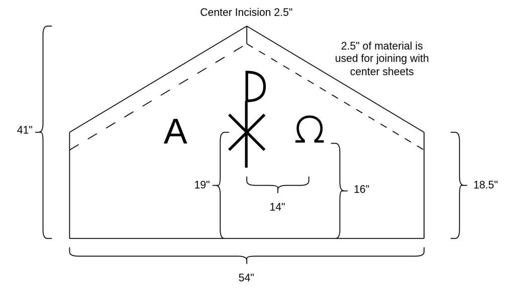
I used an off-the-shelf design for the Omega and manually sketched the patterns for the Alpha and Chi-Rho. In retrospect, the Omega would have been more visually recognizable at a distance with a “weightier” design similar to the Alpha or Chi-Rho. The Alpha was scaled to 7.5” in width and height. The Omega was scaled to 7.125” height and 7.25” width. I chose to make the Alpha slightly taller and wider because the pointed corners have less visual imprint than the rounded or block edges of the Omega. The Chi-Rho was 23” tall and 15” wide, with the center of the Chi 9.5” from the bottom of the symbol. The Alpha and Omega were set to visually “fit within” the Chi.
Bill of Materials
- 7 yds white Marine Vinyl
- 2 yds yellow Marine Vinyl
- 1 lb box of 1.25” screws
- 6x 3” screws
- 4x M10 100mm Dowel Screws
- 4x Double-Ended Clips
- 8x Eye Screws
- 12x 1/4″-20 x 2″ bolts
- 12x 1/4″-20 wingnuts
- 4x 4’ by 1.75” dowels
- 4x 3’ by 1.75” dowels
- 7x 8’ sections of 1”x2” (nominal, 1.5”x0.75” actual) PVC siding
- 8 oz of Vinyl Cement
- 2x LED lights for interior illumination
Fabrication
Poles
Drilling the holes for the dowel screws and assembling the poles: At first, I tried to make a collar wooden jig to assist in drilling the holes for the dowel screws. The jig fit snugly around the dowel and had a top piece of wood 3/4” thick. In the center of the top piece was a hole through which I could drill straight down into the dowel, with the hole providing the angular alignment. However, the small angular imprecision of the jig hole was magnified in the dowel, which made this unworkable. In the end, I was able to manually drill a hole directly in the dowel with satisfactory alignment. Part way through inserting the dowel screw into the 2nd dowel, I used the two dowel pieces as levers to adjust the angle of the interior screw by warping it. This was not apparent in the final assembly. The collar part of the jig was still useful in helping me draw an X to mark the center of the dowel end as the target for drilling. Of course, this process could have been avoided with a drill press and more formal centering tooling. Using 7’ poles would likely have been significantly more expensive due to rarity.
After joining the two dowel pieces together, I pre-drilled a small hole for the eye screws about 3/4″ from the top of the pole and inserted the eye screw that is used for the clips to the frame.
Frame
Assembly of the frame: Cutting all PVC pieces was easy with a circular saw. I sanded down any irregularities in the cut ends.
- 6x 70” – length members
- 2x 53.5” – triangle bottom pieces
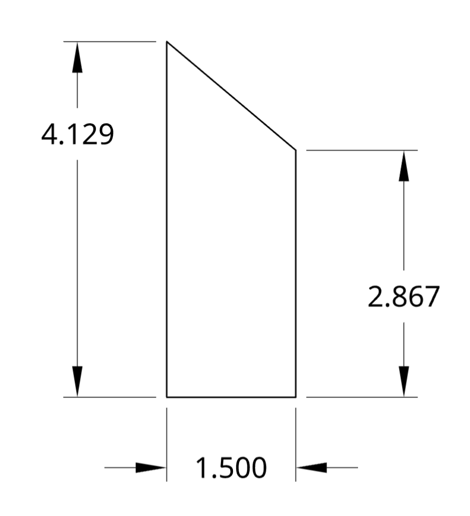
- 4x 35”, with angled cuts in – triangle side pieces (see below)
- 6x 6” – junction pieces for length members
- 2x 6” – triangle top brace pieces
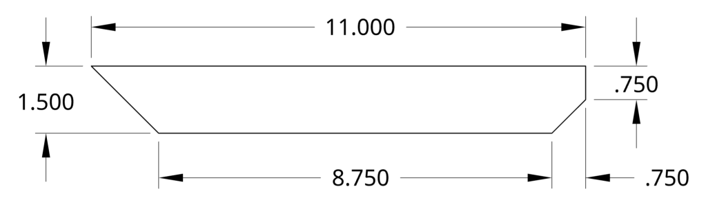
- 6x junction brace pieces (see below)
- 4x triangle side brace pieces (see below)
Triangle Frame Pieces
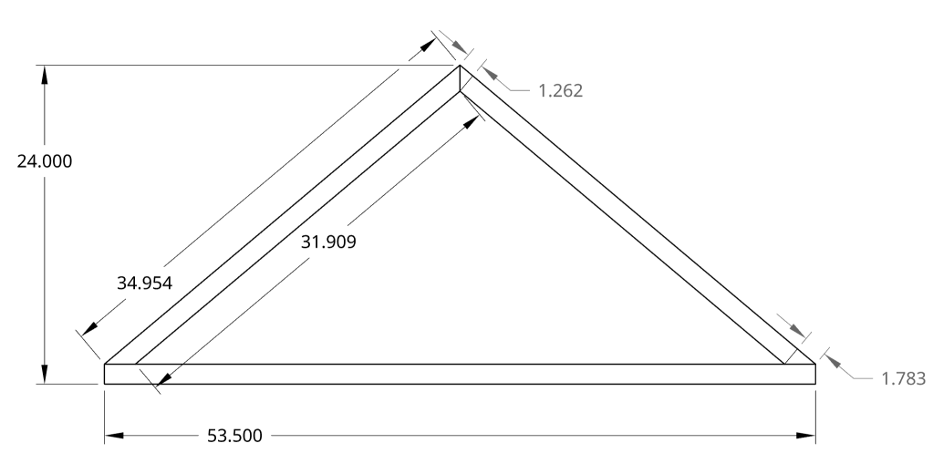
Triangle Side Brace
Junction Brace
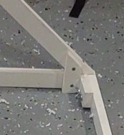
Assembly of the front and back triangles: I started with the three main pieces of each triangle and the small brace at each corner. I found that it was not necessary to pre-drill the holes. Each corner of the triangle gets a single 3” screw on its narrow side to connect it to the other main pieces and a small brace on its broad side that uses 1.25” screws. The junction and brace pieces also use 1.25” screws. Below is an example of the side corner for each triangle.
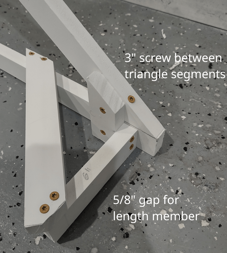
Make sure to mirror the junction at the top of the triangle for the front and back so that the broad side of the junction faces the same direction when the frame is assembled. Note that the junction piece in the below image should be flush with the triangle side on the right, not parallel to the one on the left. The ridge of the length member will still be between the two peaks because the junction was measured at 3/4” from the peak.
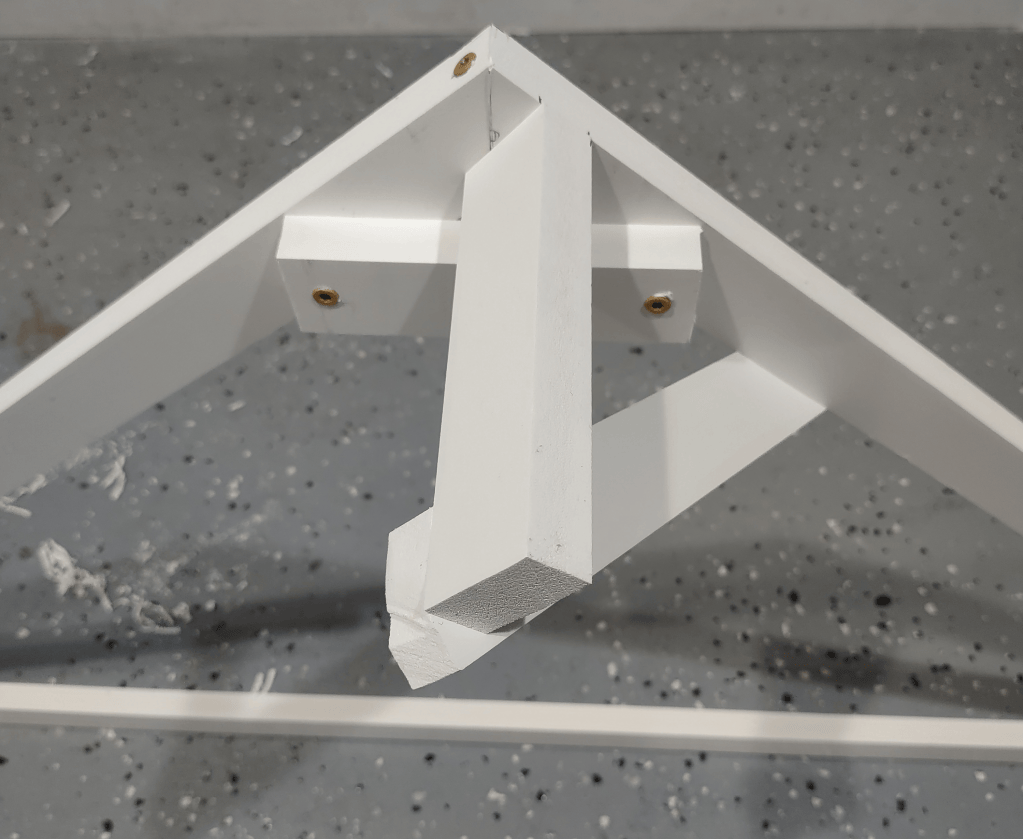
2nd Perspective on Top Junction (within full assembly)
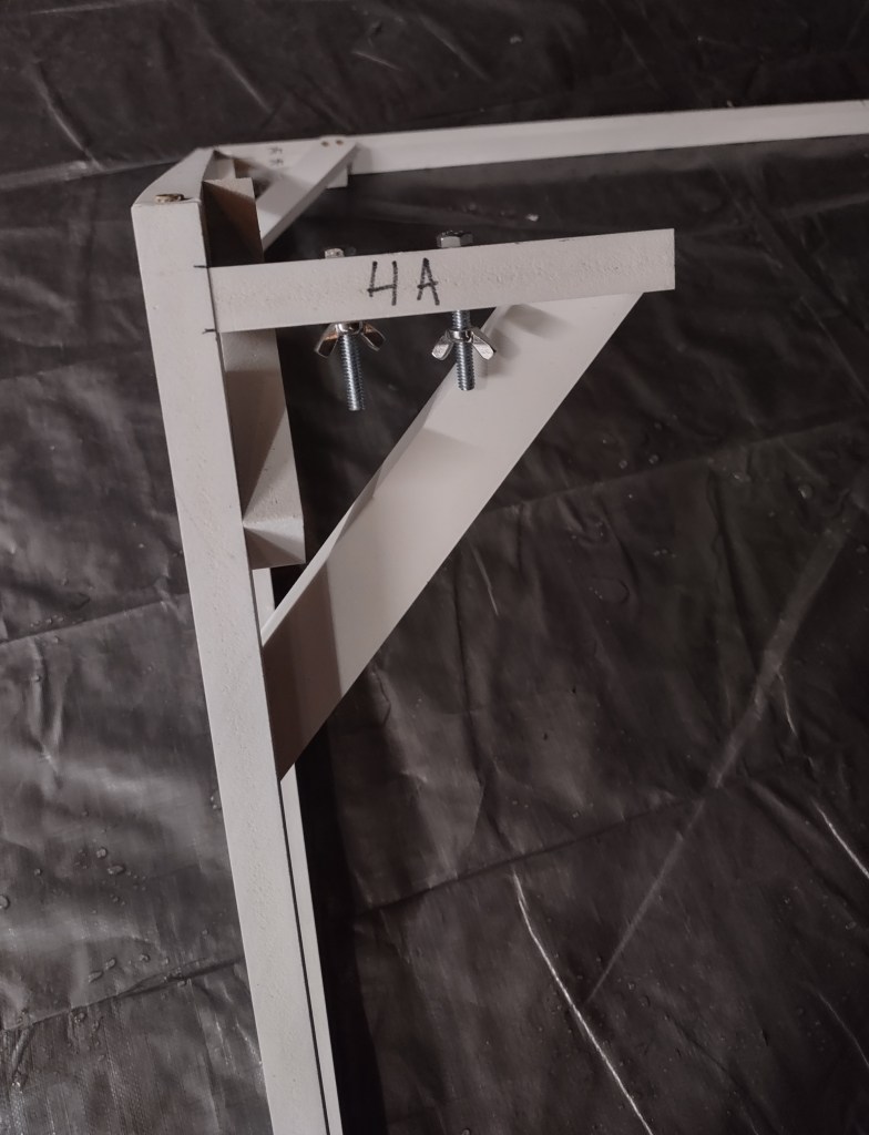
Once the front and back triangles are complete, set up the length members of the frame between the triangles. Tape the top length member to its junctions temporarily. Drill the bolt holes through the length members and the junctions as they are in place together, then insert the bolts and wing nuts as each junction is drilled. Mark which side of each length member goes with each junction.
After the cover has been fully glued together on the frame, pre-drill a small hole for the eye screws on each side face of the triangle bottom beams and insert the eye screws.
Cover
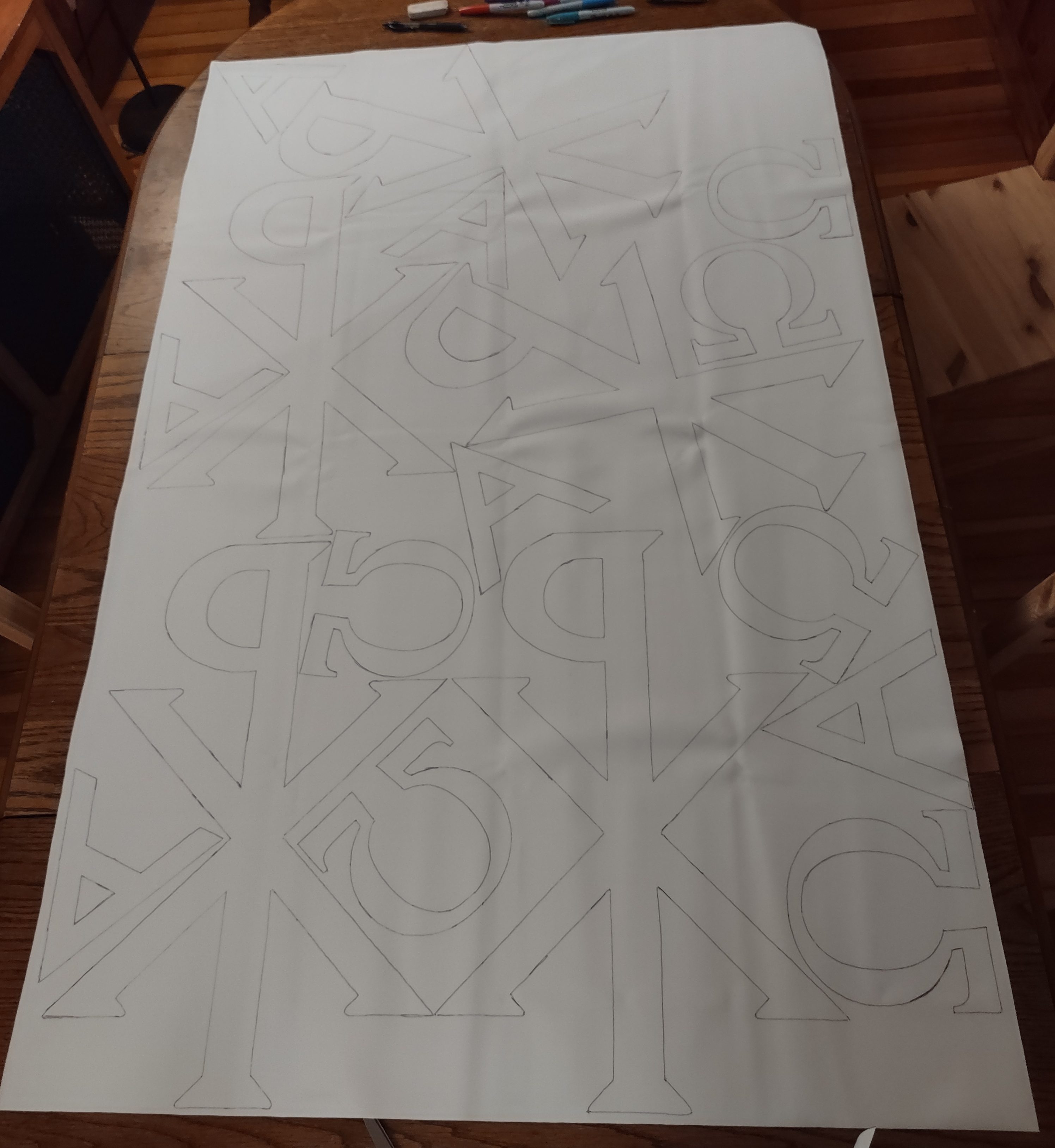
Cutting the symbols: I traced the outline of the symbols in left-right reverse on the back of the yellow vinyl. Shown below are the tracings for the symbols that would go on several of the canopies (one was made in the first iteration, three more in the second).
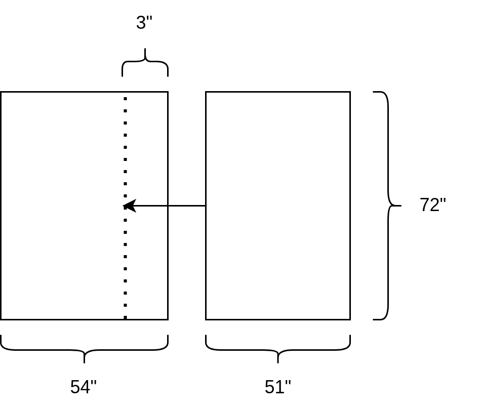
Cutting the main sheets: The lengthwise sheets are 6’ long and need to combine to be 102” wide. The vinyl bolt is nominally 54” wide and may vary, so the exact dimensions or overlap between the sheets might not exactly match the below image. Sheet sketches are not to scale.
Lengthwise Sheets – 3″ overlap for joining.
Front and Back Sheets:
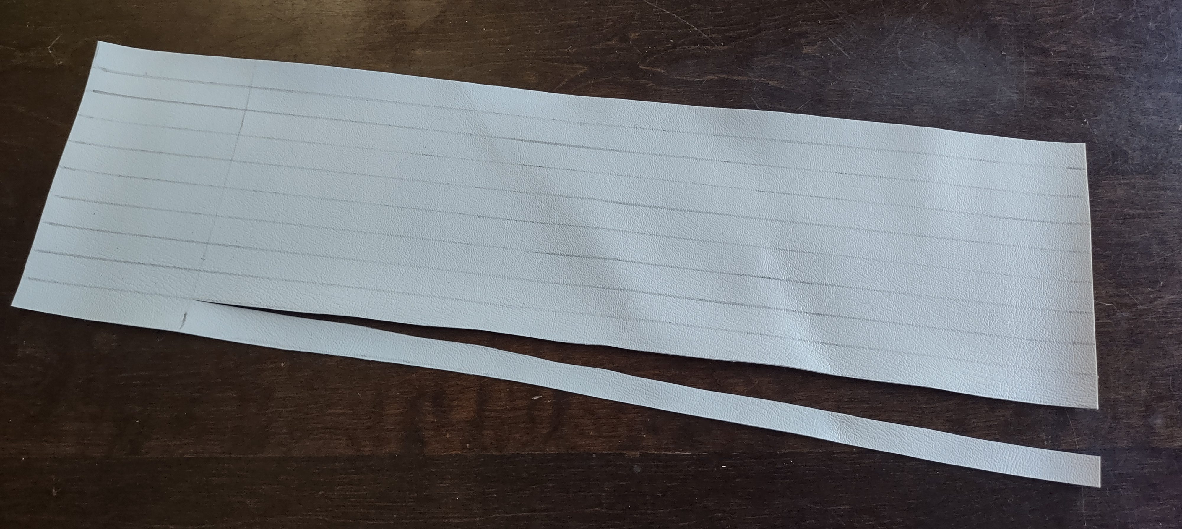
Fabric ties: We need to secure the cover to the frame in an easily reversible way. I chose to use ties made from the same Marine Vinyl fabric. The ties have one head section of 3” and two tail sections of 15”, each 1/2″ wide. The head section will be glued to the interior of the cover and the tails can be tied together around the corners of the frame. The tracing for a group of these ties is shown below.
Gluing the Cover
Marine Vinyl is easily gluable with Vinyl Cement. Vinyl cement needs to be used outside or in a room with high ventilation.
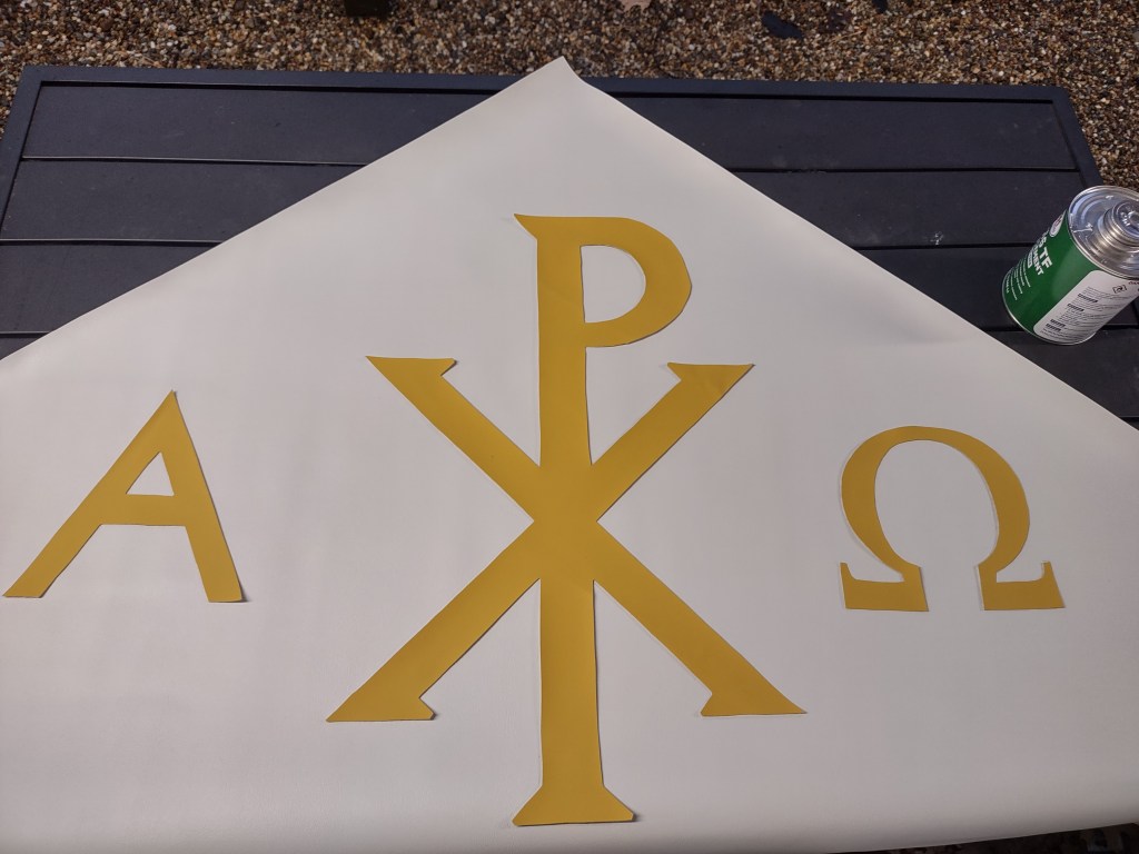
Gluing the symbols to the front and back pieces: I used a pencil to lightly trace the outlines of the symbols. I then used double-sided tape to tack the yellow vinyl symbols in place. Starting from the middle of each symbol, I folded the symbol vinyl away from the white vinyl and added glue to the white vinyl, trying to stay within the outline. Then I unfolded the symbol vinyl onto the region with glue and pressed them together. It was easier to achieve evenness in the distribution of glue over the glossy side of the white vinyl than to spread it over the back of the symbol vinyl. The recommended usage is to add the glue to both surfaces, but I found that the glue would soak in to the back of the yellow vinyl and cause it to warp. Pressing against the top of the symbol vinyl into the white vinyl got a flatter and cleaner result, even though it required adding glue only to the outlined region. When I sometimes added glue outside of that region, I was able to clean it up using the back of scrap white vinyl. The double-sided tape helped with keeping the rest of the symbol in place while portions of it were being folded or glued together. I waited about a minute after gluing each section of the symbol to allow it to set. The corners of the symbols required particular attention and sometimes slightly more glue to get a proper hold.
Gluing the trim: the 2″ yellow trim adds a small visual accent to the canopy perimeter. Similar to the symbols, we first trace the outline on the side of the front, back, and side pieces that will be at the bottom of the cover. Then we gradually add glue in sections while unfolding the yellow vinyl.
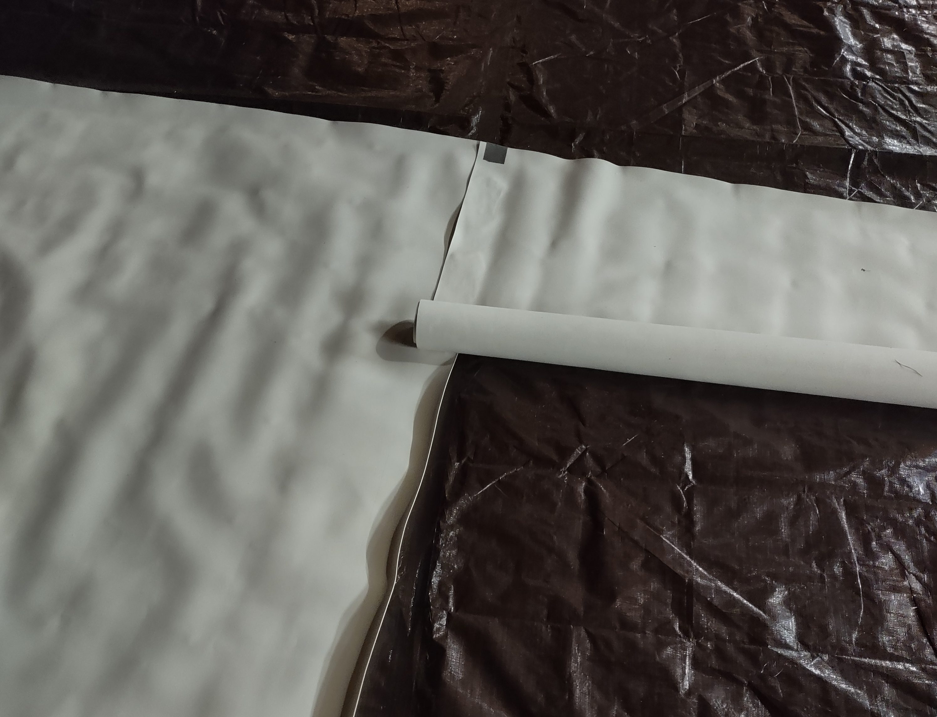
Gluing the two lengthwise pieces together: We want the lengthwise pieces to be parallel and maintain a consistent overlap region. We can cut the lengthwise pieces directly from the source bolt so that the longer sides are clean. The newly cut shorter sides will be glued to the front and back pieces with more than enough overlap, so it is OK that the cut may have some irregularity. I laid out one lengthwise piece and rolled up the 2nd piece so that it could be unrolled progressively to glue the two together. I first lightly traced the intended receiving region on the bottom piece. From there, I tacked the two pieces together using duct tape on one end, shown below. It is important to get the initial section of the two lengthwise pieces to be square against each other so that the parallelism is maintained while unrolling. Starting a few inches from the end of the cover, I gradually added sections of glue to the receiving surface and unrolled the 2nd roll onto it, briefly pressing the two pieces together and waiting. With each new section, I checked and readjusted the alignment of the two pieces. The vinyl has a little stretch to it and so permits small curves without rumpling. Finally, I went back to the section under the tape and added glue there. Doing the end sections last made it easier to make them straight.
Gluing the front and back pieces to the lengthwise cover: I chose to glue the cover together while the pieces were on top of the assembled frame to make sure the overall fit was secure but not too tight to move on and off. First, I used duct tape to tack the front and back pieces to the triangles, shown below. I checked that there was approximately 14.5” of fabric overhang at both corners, and critically that the fabric was square with the frame. Note that because the width of the frame was 53.5”, but the actual fabric may be 54-55” wide depending on the bolt, the front and back pieces will have some overhang which we trim after all gluing is complete.
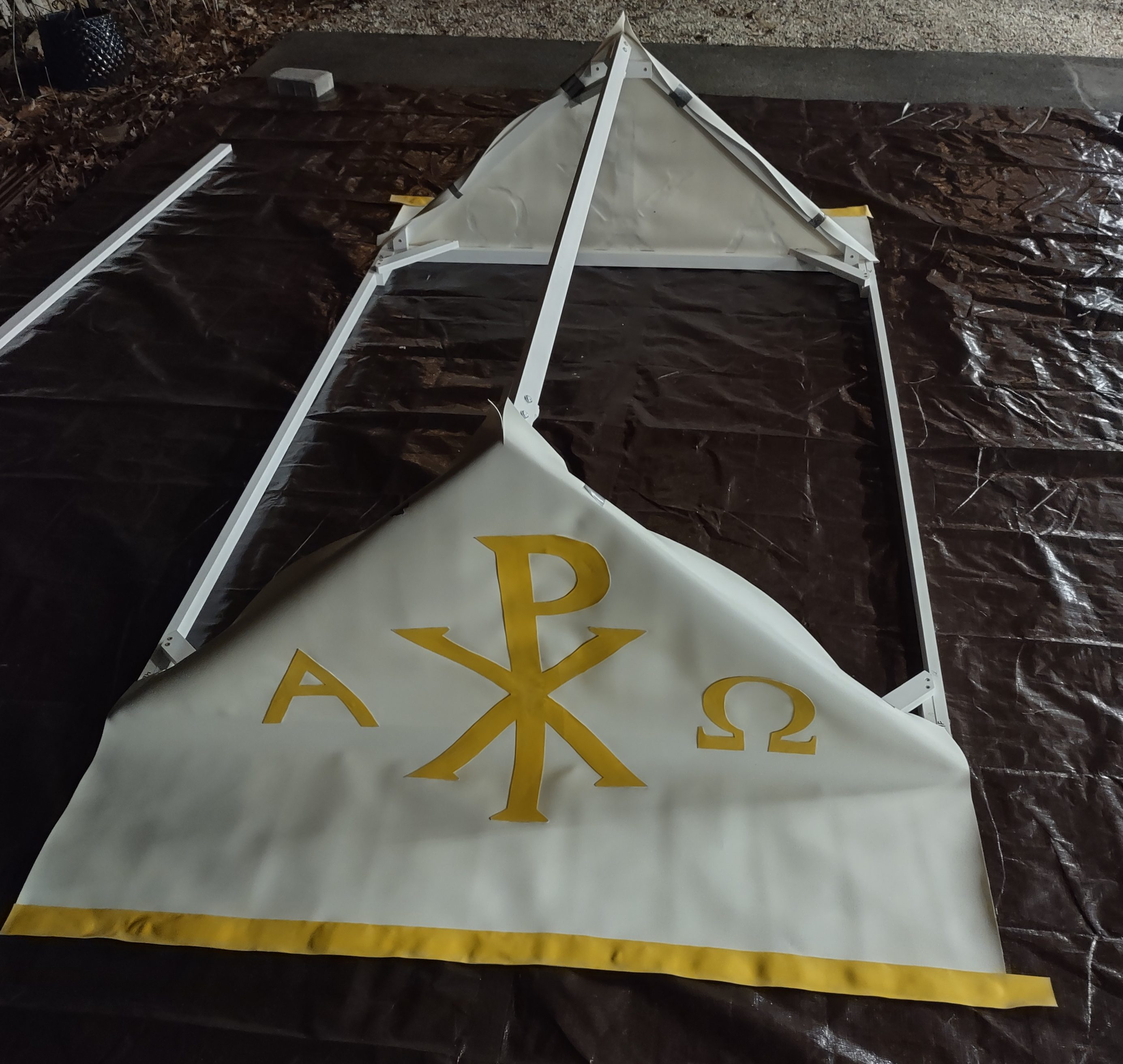
Once the front and back pieces were set, I laid the lengthwise piece over the middle and aligned the seam about 3” from the peak at both ends. I checked that the overhang of the fabric was close to even on the two sides of the frame. I then tacked the lengthwise piece to the front and back with duct tape to secure it for gluing. Finally, I worked outwards from the peak, gluing sections of about 4” at a time. I removed the exterior tacking tape as needed with each section. When complete, it looked as shown below.
Trimming the excess and making space for the eye screws: On the front and back pieces, I measured how much excess needed to be trimmed to make the sides of the overhang square with the frame. On the lengthwise piece, I measured the length of the sides needed to expose the 3/4” thickness of the front and back beams, and trimmed that amount. This cut is needed so that the cover doesn’t sit on top of the eye screws that connect the poles to the frame.
Fabric Ties: Glue the fabric ties to the interior of the cover near the corners of the lengthwise piece, set back from where the frame will match against the cover by about 2”. As before, apply the glue to the glossy side first and press the two pieces together. In the first iteration, I manually sewed the ties into the cover, but this created tears in the fabric and some of the ties eventually ripped out. Gluing was more secure and did not create tears.
Canopy In Use



Usage Instructions
The following usage instructions are written to stand alone for users of the canopies, so some of the content is repeated from above.
Assembly/Disassembly
There are three major components of the canopy: the frame, the cover, and the poles. Start by assembling the frame. When assembled, the frame looks like the following image (minus the duct tape). The frame is 53.5” wide, 71.5” long, and 24” inches tall.
The frame is disassembled to be transported into the two triangles and three beams. The triangles are connected with bolts and wing nuts to the beams. In the below images, you can see the wing nuts in place on the bolts that go through the two bolt holes that are on each side of each beam.
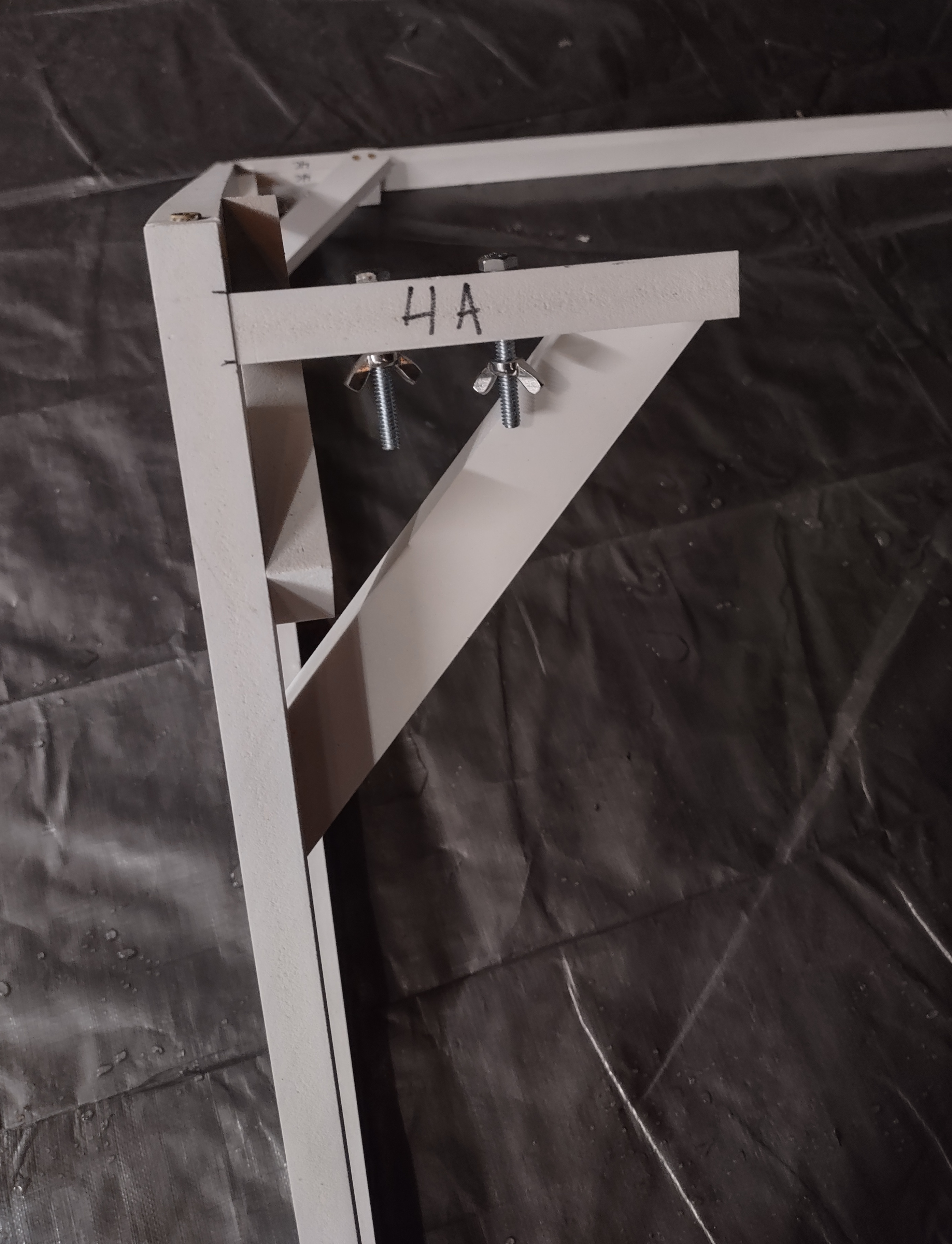
On the completed frame, you will notice that there are numbers and letters on each point of the triangles and each side of the beams. The numbers and letters must match for the pieces to fit together. All frames are unique due to their manual creation. The bolt holes were drilled manually and so only match within each specific frame. The number is the serial number of the canopy and the letter is the position of the junction on the frame. The image on the right shows an example of the number and letter on one junction point of a triangle. When disassembling the frame for transportation or storage, be sure to put the bolts through the bolt holes and fasten the wing nuts. This will prevent the pieces from getting lost.
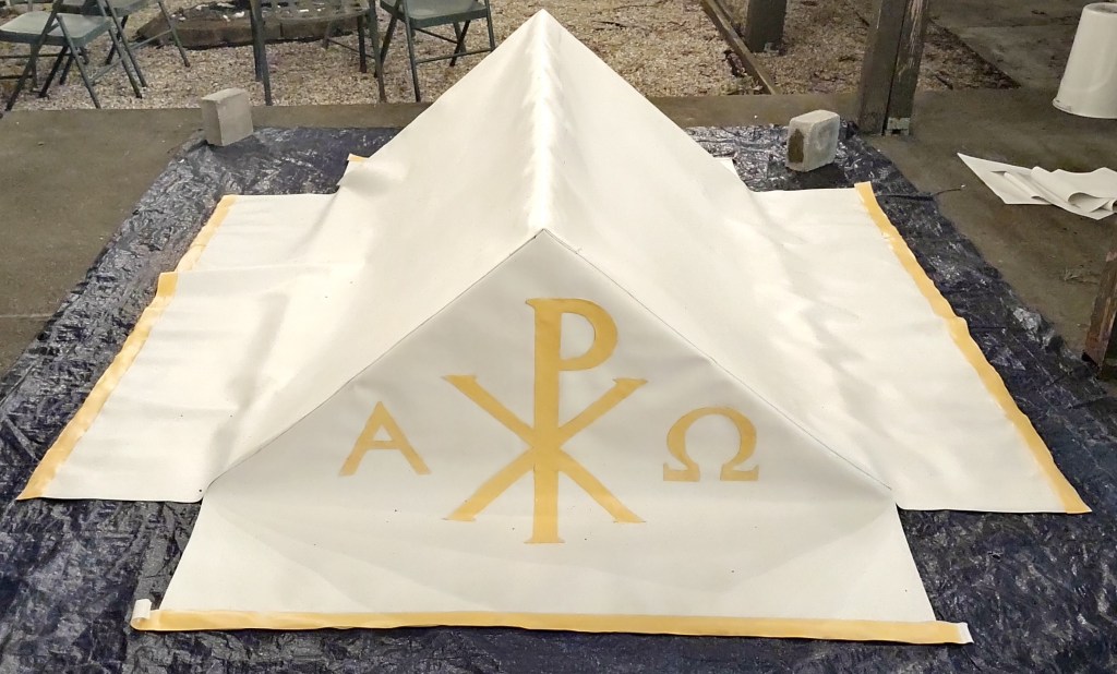
Once you have assembled the frame, unfold the cover and place it over the frame. On the ground, it will look similar to the below image (the excess yellow trim was removed after this picture). The cover is 72” long, so there is about 1/2” of tolerance between the frame and the cover to allow for easy assembly and removal.
At each of the corners of the cover on the ground that are adjacent to the corners of the triangles, there are fabric ties to secure the cover in place. Tie them around the corner of the assembled frame. Finally, connect the poles to the frame with the double-sided clips. The poles are 7’ tall. In use, it looks like the following image:
After use, be sure to keep the clips connected to the triangles so that they do not get lost. The poles are 84” long, while the beams are 70” long, meaning that storing and transporting the assembled poles does not take much more space than the beams themselves. It is recommended to not disassemble the poles for storage so as to not wear out the interior of the wood from repeated screwing and unscrewing which will make the junction weaker.
Processing with the Canopy
The canopy frame is intentionally rigid so that rain water flows off the sides. This means that it is important to be aware of any obstructions in its path while processing and route around them. The responsibilities of the front bearers are to look out for obstacles and occasionally look to the side to confirm height alignment with the other front bearer. The rear bearers should look ahead and try to keep the frame level with the front bearers. The clips on the corners of the frame are not rigid and allow for some tolerance in the relative position of the poles. However, the bearers should still try to walk in unison. Bearers should practice walking with the canopy before the procession to learn how to travel together and hold the canopy at a consistent height.
Folding the Cover
If the canopy needs to be stored or transported, try to fold the cover primarily along its major seams. The front and back pieces can be creased at their middles with the side piece lying flat at the ground. Then, fold the front and back pieces inward, and once again in the middle of the side pieces. This will minimize the number of creases in the cover. The creases should also come out naturally after the cover has spent time in the fully assembled canopy form.
Cleaning the cover
The cover is made from marine vinyl, which is naturally waterproof. If the cover gets soiled or dirty, rub it with a wet cloth with dish soap. Be sure to dry it before folding it because the water will be trapped otherwise. More extensive cleaning is possible but requires specialty cleaners.
Patching the cover
If for any reason the cover gets torn, spare marine vinyl can be used to patch it. A piece that is about 2” wider than the tear on all sides should be glued on the interior of the cover.

