What is the right curriculum to achieve the envisioned outcomes for software engineers? I propose that such a curriculum has four interwoven disciplinary threads with the desired professional skills and mindset integrated into their courses. The four threads are:
Computers as Formal Systems: Programming languages are unlike natural languages in that their statements mean exactly one thing. Any piece of code is a definite specification of operations or “instructions” that the “processing units” of a computer will perform. Instructions are simple arithmetical operations and movements of stored data, but they can be built up into extremely powerful tools. This thread starts with treating a computer like a ‘big calculator’ to crunch numbers to understand the behavior of physical systems in “Modeling and Simulation”, develops with the systematic construction of software, and reaches its completion with the theoretical foundation of what computers can do in “Foundations of Computer Science”.
Modeling and Simulation, Software Design, Discrete Math, Data Structures and Algorithms, Computer Architecture, Software Systems, Databases, Foundations of Computer Science.
Computers for Mathematical Analysis: Engineers work with data, and data from the real world is noisy! Processing large volumes of data requires computers. Engineers need to learn how to use computers to collect data, manipulate it, draw inferences from it, and present it to people in a way they can understand. This thread begins with a foundation in Probability, Statistics, and Linear Algebra, progresses through Machine Learning (automated pattern recognition) and serves as the basis for the mindset of experimental design.
Modeling and Simulation, Linear Algebra, Probability and Statistics, Machine Learning I: Tabular, Data Visualization, Machine Learning II: Computer Vision, Computational Robotics.
Computers in Integrated Products: We can use computers not only to do math, but also in embedded physical systems that do things in the real world. Once we physically deploy complete systems, the fun of integration challenges begins! This is a sequence of integrated hardware, electrical, and software projects that cultivates the mindset of building full products with computation at their core.
Real World Measurements, Fundamentals of Robotics, Computational Robotics.
Human Context of Engineering: Engineers build things for people with other engineers. How do we design the right products for our users, along with them? How do we communicate our mathematical analyses and experimental results? How do we learn from and teach others? And then how do we integrate all of our technical and interpersonal skills into human organizations that build things together? This thread has several courses explicitly within it, but permeates through the curriculum.
User-Oriented Design, Data Visualization, Teaching and Learning, Venture Management.
While these threads are presented distinctly for clarity of communication, the knowledge and skills they impart are all tied together. This particular example of an “Open Software Engineering Curriculum” (OSEC) has eight “phases” that could roughly correspond to eight semesters, or eight increments of independent study. With eight semesters, there is plenty of room for “distribution requirements”. Each pair of phases (I and II, III and IV, etc.) could be done simultaneously to compress the sequence into two years without other courses included. Each pair contains a course with a substantial team project, highlighted in green. There are seven underlined courses that lend themselves to the creation of projects that are suitable for a “portfolio”.
As described in the “Structured Exploration” and “Mindset” chapters, this curriculum is designed to promote a proactive approach to learning, teamwork, user orientation, and long-term systems thinking. These themes are introduced early in the sequence so that they can be cultivated over time.
OSEC, as a project, is mostly a work of curation and “restyling” existing content to better promote the proposed outcomes. Almost all of the named courses correspond to well-known pedagogical modules which are listed as references. These references will be incrementally reworked and further curated. I have intentionally “tied” certain modules together in the sequence that ought to be taught within a single block. Because software engineers are primarily practitioners, learning of math is tied to application within this curriculum.
The intention of this OSEC is to present a comprehensive and explainable course sequence. Compare this to the MIT Computer Science and Engineering requirements and outcomes documents. Instead of merely listing the content, this is meant to explain how it all fits together.
Courses
Real World Measurements: Arduino C:
Imagine a “weather station” that monitors wind speed, rain, humidity, sunlight, etc. and is physically deployed. To put together such a weather station requires integration of microcontrollers and basic circuits, as well as simple mechanical design to enclose it and make it resistant to the elements. The physical system must be maintained through time, over months or even years, and can be progressively improved in response to problems. Once it is deployed as a system and reporting data, the data stream can be processed and uploaded to the cloud. Visualizations can be built on the data stream as a simple website. The data set presents opportunities for analysis and predictive modeling. Multiple stations can communicate as a mesh network. Starting from even a simple measurement device, there are many avenues for problem-based technical depth within software engineering across the product life cycle. The practice of physical and software maintenance within this project helps to prevent a mindset in which “everyone wants to invent the future, but no one wants to be on the future’s on-call rotation”. All of the technical features are built upon the continuous proper functioning of this device and data pipeline.
This is the central project within this course, but there can be other kinds of sensor integration possible. Its location at the beginning of the curriculum is to introduce ideas of system integration (HW, EE, SW) and long-term maintenance. For the sake of simplicity of management and ensuring good learning for each student, this is not naturally a team project.
Budget for Arduino, servos, sensors, lights, wires – roughly $200.
Data can be used as the basis for future courses: Modeling and Simulation, ProbStat, Machine Learning, Data Visualization.
Students can learn how to care about long-term effects and sustainability of products for the people using them simply by working with them over longer periods of time. Olin’s “Engineering for Humanity” is an introductory design course that pairs students with seniors and has them try to solve problems that they face, often centered on negotiating the physical environment. Working with seniors in this way has many advantages: physical objects are often not easy for them to use, and so there are plenty of opportunities for assisting them. Solutions can be inexpensive. Seniors are often overlooked, generally have a lot of free time, and are happy to talk to young people who want to help them, so they are an ideal user group. By extending this engagement beyond a semester-long course and doing long-term support for these projects, students can gain an appreciation for lasting impacts on users as well as technical sustainability.
This is located at the beginning of the curriculum to plant the seed of thinking about impact on the end user. Some students enter into engineering just wanting to create something that is cool, and not on the end result, or might be hesitant to engage with people. Seniors naturally want to talk to them, so they are a great group to start with.
Modeling and Simulation, Probability and Statistics, Linear Algebra
Topics: Weather Forecasting, Stocks and Flows, Simple mechanics and thermal simulation, Introduction of datasets that require probabilistic modeling, Introduction to Bayesian and Frequentist statistics, Monte Carlo Methods, Transformation of physical systems through time, Introduction of Linear Programming, Optimization Approaches.
Methodical design of software and learning the mathematical basis of software systems. Object Oriented Design, Modularity within software projects, Introducing time and space complexity analysis. Building a video game as a group to introduce collaborative SW development, simple user experience testing, Model View Control design pattern.
Discrete Math is often mistakenly taught after the introductory software “design” course, but this is wasteful because all of its concepts are naturally included in learning the theory of software. Software projects can be chosen to illustrate different ideas within Discrete Math. Formal thinking and constructing proofs of mathematical relations introduces students to the idea of computers as mathematical symbolic manipulation machines instead of just tools. It would be wrong to start with the theory and postpone “building things with computers” until after the math.
Machine Learning I: Tabular and Data Visualization
Analysis of datasets and “statistical learning” leading to close examination of the data and its distributions. Emphasis on communication to people in general interest technical writing alongside purpose-driven visualizations. Making a simple website for these artifacts. Understanding how pattern recognition can be automated. Can build upon the weather station data. Creating ML models of physical processes: this is an advancement over the simpler approaches introduced in Modeling and Simulation / Linear Algebra. Includes (review of) necessary Calculus concepts. “Citizen Data Science”: using data visualization and modeling to present an argument about some topic of public interest. This is an exercise in public communication through data. Accuracy of analysis and presentation is key.
Building integrated mechanical, electrical, and software systems in a team. Characterization of motors. Build a simple robot that moves in the world in response to sensor input. After this course, students are well-posed to mentor a high school robotics team.
Starting in phase V, transition from foundational learning to specialized learning. Engagement with high school students or earlier learners of this curriculum in a teaching or mentoring capacity. Mentoring is a core engineering skill for the sake of organizational sustainability and learning how to communicate to more junior people is a completely different mindset from communicating to professors who know more about the subject. After the “Citizen Data Science” from “Data Visualization”, communication deepens by teaching others technical subjects.
Emphasized Skills: Communication, Mentoring, Reflection on Process of Learning
Classical computer vision techniques, Convolutional Neural Networks, Transformers. Data augmentation. Object Detection, Segmentation. Animal identification in the wild, which can be integrated into the “weather station”, then relate presence of animals to environmental conditions.
Introduction to: Operating Systems, Web Servers, Networks & Distributed Systems, Database Management, System Performance Analysis. Emphasis on detailed design reviews of peer’s artifacts.
How do we integrate all of our technical and interpersonal skills into human organizations that build things together?
As of 2023/09/21: Open question on whether this should attempt a practical component of operating a business. I am more skeptical of this because it is difficult to make actual business operations self-contained within the scope of a course and still be a meaningful management experience. Current plan is that this would primarily include the curation of case studies and readings on management with exercises in opportunity assessment via interviewing hypothetical users and creating a business plan.
Theory of Automata, Turing Machines, Computability, Functional Programming. Standard approach would be to focus solely on the proofs. Intention in this course is to actually implement ‘automata’ in OCaml.
How should work be reviewed and considered as worthy to publish or put into production? Engineering teams building products need to have processes for review and approval. On student teams, these standards may be unclear. In a professional setting, there are a few major patterns with the most important artifacts like code and externally-facing documentation going through established processes. But smaller artifacts like internal documentation or minor designs might not. In every setting, it is valuable to have agreement within the team about what the review and approval standards are. Misunderstandings about approval systems are common especially within student teams and can be easily prevented with early discussion.
1. Consensus: Some teams may wish to have consensus among all members before making any significant decision. This is typically unrealistic and violates the principle of unity of ownership. Someone must own the ultimate choice and be responsible for its implementation. Even after everyone has had the opportunity to raise their arguments for and against each design option, some may be unpersuaded. There might be insufficient funding or time to test each option and a singular decision may be necessary (a “one-way door decision”).
Some may believe that consensus is the default approval mechanism. While it may be possible on student projects in which the stakes are lower, it should be avoided in favor of subdividing ownership and adopting a different approval system for each component.
2. Majority: Others may wish to have major questions decided by majority vote. This also violates the principle of unity of ownership, because no artifact is owned by the majority but instead by specific contributors. In student teams without a clear leader or manager, this may seem attractive as alternative to Consensus in the face of one or two persistently dissenting voices, but does not resolve the core problem of ownership of specific components.
3. Reviewer Pattern: An implementer or author creates an artifact and must get agreement from others for it to be considered valid for promotion. This is typical for code artifacts which should require at least one other developer before being put into the testing and deployment pipeline. The implementer owns the solution, but the reviewer owns the examination of it and making sure it follows team standards. The implementer owns the incorporation of feedback from the reviewer. The reviewer still controls its final approval.
4. Commentator Pattern: An author creates an artifact and solicits feedback from others, but addressing this feedback is not considered mandatory for promotion or publication of it. This is faster than the Reviewer Pattern, but usually does not achieve the same level of quality control. The Commentator pattern is more common for some kinds of internal documentation.
5. Retroactive Audit: Decisions are recorded and available for future review by the team. This maintains accountability while allowing individuals to make quick decisions. Small purchases and rapid prototyping benefit from high speed and retroactive auditability instead of proactive review.
For example, when preparing a group presentation, how should it be reviewed? The common practice is to give certain slides to specific people. But does that contributor have the final decision on that content? This should be discussed within the team at the beginning of the preparation of the presentation. If the presentation requires some consistency of content, then it might be valuable to make the Reviewer Pattern explicit at the beginning. If this isn’t clear, and one contributor’s artifacts come under criticism from the rest of the team, then that person may feel unfairly targeted and undermined if he implicitly believed the Commentator Pattern was being used. If the common understanding is that everyone’s slides need to be approved by at least one other person, then that minimizes the chance of frustration.
Clarity of approval patterns further improves team cohesion.
How should people who enjoy building things and have aptitude in math and science become engineers? Answering this is our quest. This is intentionally different from asking ‘how should engineering be taught?’ or ‘what is the right structure for engineering courses?’ because engineering is not merely a body of content that passes from the teacher to the student. It is a mindset and a collection of habits in addition to an evolving base of knowledge.
We will first compare two different approaches to engineering education and then introduce a third that we believe better aligns with our proposed habit formation goals. The most established and common form of education is “Direct Instruction” (DI), and Olin and other schools have responded to this with a different system that I will rename for clarity as “Structured Exploration” (SE) though it is known internally as “Do-Learn”.
In Direct Instruction, students do readings in preparation for class, attend lectures, do problem sets, do explicitly structured laboratory experiments, take tests, and may do a final project for the course. This is the traditional pattern familiar to students of most technical subjects. DI has many advantages: It is easy to design courses with this format and simple to teach. Students already understand this pattern from prior schooling. Because concepts build upon each other within and between courses, the dependency chain of prerequisites is clear. The curriculum becomes straightforwardly modular and easily reviewable by others. However, its format does not prepare students for the practice of engineering. When building something new, the formal theory is often not known beforehand. Even if the scientific knowledge exists, the process of discovering it and learning how to apply it to solve problems does not come with an answer key. Aspiring engineers must learn how to explore a new field by familiarizing themselves with the relevant literature, designing experiments that answer open technical questions, and then ordering the construction of prototypes to develop new technology. DI does not incorporate this uncertainty. Even though the didactic DI approach makes course design simple, it allows students to follow from the conceptual sequence of the readings and lectures instead of requiring them to contend with unclear problems. Further, by focusing on pure reception of content, DI risks losing the “joy of building” that motivated most students to pursue engineering.
What if the pattern were flipped such that building new things drove learning? This is the premise of ‘Do-Learn’ or ‘Structured Exploration’, and ‘experiential learning’. In DI, the learning precedes the application in what is usually a limited final project in the course or senior project. In SE, students are given an application and some ‘structure’ such as relevant papers, book chapters, or hardware and need to ‘explore’ the domain to build it. Then, there is formal treatment and review of the content necessary for the problem alongside a report.
We can take the example of an early Olin class project in “A Whole New Engineer” (p. 21) for SE: Professor Gill Pratt “challenged students to design and build a pulse oximeter (a device that measures your pulse and blood oxygenation) during the first six-week module. Rather than starting with lectures about circuits, he introduced the idea of what a pulse oximeter is and conceptually how it works and then acted as a coach as students began to wrestle with the concept. Students read patents; they built simple circuits; they blew up simple circuits – but at the end of six weeks, they had successfully constructed a working pulse oximeter. It wasn’t pretty; it didn’t work as well as a commercial device, but it worked, despite the fact that the students who built it had just finished high school and had never worked with circuits before.” Building the pulse oximeter motivated learning.
To design courses in the SE style, professors select problems that will illustrate certain concepts and allow students to discover them. This improves student ownership over learning instead of treating it as something that is simply received. Software Engineering needs this more than other fields because it changes more rapidly. What one’s professors learned probably came from a different era. Further, because software engineers may work on automation or optimization solutions for many different domains in their careers, they especially need to develop this concept acquisition skill. Through its curated structure, SE serves as scaffolding to the experience of diving into a new domain. Courses should offer progressively less of this structure through the curriculum to gradually build student autonomy.
Compared with DI, SE better prepares students to engage with uncertainty and builds their confidence in their ability to learn in a self-directed manner. It shows how theoretical knowledge and its acquisition relates to practical implementation. Student’s motivation to build can help propel them through the curriculum instead of something that happens on the side or late in their studies.
However, there are also many costs to SE, which may be under-reported by its advocates. First, it can be a source of anxiety for many students, especially those who are falling behind. While engaging with the ambiguity of a problem can be exciting for those on top of their work, for those who are struggling it can appear as an unnecessary obstacle or cause of frustration. In DI, students can work through an established course structure that is laid out clearly on the syllabus. They can draw from their familiar study habits to churn through the readings and the problem sets. If the course does not make it clear how all the concepts that should have been encountered through each lab or experiment fit together, then the big picture can also be lost. Missed connections then can compound over the course of the curriculum.
Second, developing a curriculum composed mostly of structured explorations requires much more effort than DI. Each exploration needs to illustrate the intended principles while having scope reasonable for a course. The treatment of each topic will naturally take longer because it must allow for false starts and failed experiments within student exploration. Third, SE courses are harder to make legible: other instructors even at the same institution may have difficulty reviewing the course plan, and might not be able to rely as strongly on the coverage of certain topics in courses intended as prerequisites, or student retention of them. In traditional DI, each course functions as a well-understood module in the curriculum that facilitates communication and planning. Fourth, measuring student progress becomes harder, especially for individual contribution in team projects. All of these are acknowledged trade-offs for the sake of promoting a habit-forming learning experience that better matches engineering practice.
But the most serious problem with SE as it is frequently implemented is that it does not actually ‘complete the cycle’ of engineering practice with reviewed iteration. “Do-Learn” promises that the formal learning happens alongside and partially after the first practical engagement with the material. Without taking the results of the first exploration, presenting them to peers, and re-doing the design, SE only covers the first steps of the engineering process. A proof of concept for a pulse oximeter is only the beginning. Instead, we propose “Crystallized Engagement” (CE) as Exploration, Formal Theory, and Integrated Application: first gain hands-on experience and learn the theory in parallel, then do it again while methodically applying the theoretical knowledge. In DI and SE, student projects often turn into proofs of concept that barely work for the demo in front of the class and are then forgotten. While rapid prototyping is a valuable skill, engineering as a discipline requires analyzing failure modes and getting systems to work reliably. Finally, engineers need to be able to pass the baton to others through technical review and complete documentation. The curriculum should include all of these steps for comprehensive preparation. The first completion of the engineering cycle directs students to ‘begin with the end in mind’ of an intentionally designed, reliable, and well-documented system, instead of staying in a tinkering mindset.
This proposed Crystallized Engagement takes even longer than Structured Exploration by requiring additional iterations on specific projects. However, it does not need to be used in every course, just as the time investment for SE might not be everywhere justified. Given that these approaches aim to develop engineering mindsets and skills, it is likely sufficient to introduce them early to ‘plant the seed’ of these ideas and then allow them to naturally grow through the curriculum through a variety of projects. It is difficult to avoid sacrificing breadth for depth with this approach, but because we have the engineering mindset as a core goal, we believe it is worthwhile.
What motivates people to learn? How could the structure of education be changed to promote student motivation? Could these changes be made outside of a traditional classroom or course setting?
Theorists of motivation have put forward two main types: intrinsic and extrinsic motivation. Intrinsic motivation is a desire for a thing for its own sake. Extrinsic motivation is desire for something as a means to another goal, or to fulfill someone else’s expectations. Edward Deci and other pedagogical theorists argue that intrinsic motivation leads to deeper comprehension of a field and overall better learning outcomes, and that students who are motivated only by grades and social expectations are less likely to strive for excellence, retain knowledge, and make future contributions.
While I think it is clear that students who truly desire learning for its own sake will learn more, in practice, personal motivation is rarely clearly separated into these different types. For the great mass of people, even those who will likely go into the professional world, motivation to learn is a mixture of desires: curiosity, enjoyment of the subject, wishing to enter a well-paying or respected field, fulfillment of expectations of parents or teachers, to keep up with one’s peers, to be better than one’s peers, to be a good student as a matter of personal identity, to make good on one’s investment in education, intending to use the skills gained to help others, etc.
Further, there are very few people who have sufficient internal motivation to carry them through an entire course of study, regardless of initial interest. Consider those who enroll in Massive Online Open Courses. Some may wish to gain a skill for practical career growth, but most do start with meaningful intrinsic motivation. Why do so many fail to complete these courses? For most people, either they had a mistaken impression of the field, or their interest didn’t match up to the effort required.
Online learning lacks the typical sources of extrinsic motivation that a traditional classroom setting has. Physical presence engenders types of motivation that cannot be replicated online:
Mimetic Desire: When students sit in a class and face a lecturer or each other in a studio setting, they have learning as a socially acknowledged common object of desire. Online lectures, even if synchronous, do not create the same psychological response.
Cohort Maintenance: students wish to keep up with others in the same cohort who are sitting around them. People don’t perceive other participants in a video conference in the same way.
Friendship: In Aristotle’s framing, they can form friendships both of utility in their learning and peer tutoring, and of the cultivation of virtue as students. Being a good student becomes part of being a good friend.
Location-based Habit: a classroom is a physical setting for learning, as a space that is marked apart, and presence in it helps to set one’s mind to the task. Presence is an investment in the pursuit of learning that builds to further effort.
Integrity of Identity: Further, presence commits one to the identity of being a student. Once you say to yourself, “I am a student”, it should naturally lead to thinking “I want to be a good student”, then that learning and studiousness are good, and that it is desirable to learn the subject for its own sake. This is a ladder from extrinsic to intrinsic motivation.
These are some of the reasons, which in my view are under-appreciated, for why in-person lectures help to carry one’s interest through the troughs of motivation. A self-motivated learner can watch a series of video lectures, take notes, do the readings, work through the exercises, seek out help on forums online, and even devise projects to apply the skills. But for most learners who do not have the same level of interior motivation, the sources based in a physical community are invaluable to sustain interest, even though they are mostly extrinsic.
With all of these benefits of physical presence, is there any hope for the efficacious adoption of online courses outside of the highly motivated minority?
Here I will try to sketch an answer that gains the benefits of an in-person community while not requiring the traditional classroom structure. Content distribution, in itself, has effectively zero marginal cost. The best static content: readings, video lectures, problem sets, and project prompts can be distributed for free. This was the promise of MOOCs – but they lacked the motivational structure. The online ‘community’ was not meaningfully better than that of existing forums or Stack Exchange. How can we join this content to a real community?
“Company” Cohort Formation through Pizza Subscription:
Eating together is the root of companionship, and growing together in learning makes a cohort. What if we could form “learning pacts” with “pizza subscriptions”?
In the same way that people find training buddies to go to the gym at regular times, students naturally also form study groups with others of similar skill. Training buddies in a “gym pact” help to create the kinds of motivation formed through community and social expectation discussed above. Going to a gym with the same set of friends builds a habit. The college cafeteria serves a similar purpose: it builds companionship among a group of learners. Enrollment is not a purchase of content: it is buying entrance into a learning pact and community. But we should be able to create such pacts at much lower cost than college today.
There are three parties to this pact: the students, the content creators, and the “cafeterias”. Imagine a “pizza subscription” that is tied to the purchase of an online course: “Buy this online course content, and every Tuesday night for 15 weeks, get 2 pies at a 10% discount if you pay upfront”. Students who want the benefits of such a pact can find others with whom they can jointly purchase this subscription. The subscription is a costly signal of commitment to the group. Once they buy the subscription, eating there is cheaper than any other option, which motivates them to go, in addition to seeing their friends. Students who have purchased such subscriptions are connected together on an online forum to discuss course content. Participants watch lectures and do readings outside of the meeting times, and get together to work on problem sets and projects. Any venue with under-utilized function space and WiFi that serves food can serve as a meeting spot. Restaurants want regular business and to get paid before the goods are delivered. They can also load-balance their business by offering promotions on specific days. Content creators want to sell courses with zero marginal cost. They can take a cut of the subscription. To tie all of the motivation together, when purchasing the subscription, the group also sends a calendar invitation to their friends and members of other such learning pacts for their final project presentation which happens at the end of the course. This functions in the same way as signing up for a future race at the beginning of a training program. The project is an opportunity to practice teamwork and then becomes part of each student’s portfolio. To gain high-level direction and guidance on theoretical depth that is difficult to obtain from forums, hire a graduate student for 5-10 hours of 1:1 or group tutoring through the course. I believe that what I have described here is a Pareto of the college educational experience for a tiny fraction of the cost.
Cost: Suppose 3 friends each pay $200 dollars for a 15 week food subscription, plus access to course content, and the cut of the course is $100 of the sum. The access to the course isn’t a necessary component of this because there are plenty of free courses online, but including it completes the picture. There are plenty of inexpensive restaurants that should be able to profitably serve $11/person/meal especially for regular business that is paid in advance. Posed differently, it is two pizzas for $33 for repeat business on a slow night. Restaurant chains could partner with this “subscription originator” to economize the organizational overhead of coordinating the promotions. The marginal cost to the student is about $8/meal over making one’s own food, or $120 in total. A graduate student tutor would cost a few hundred dollars more.
Team Formation: Forming such groups with friends is ideal, but not everyone has friends looking to study the same things at the same time. What would matchmaking between students require? Indication of interest, availability, and possibly some test of skill. Depending on the subject, there may already be forms of online assessment to automate this testing. Tools like ChatGPT can complicate such assessment, but as a tool that will become part of one’s toolbox, they could also be allowed. Teams should be in groups of 2-4. Even if mismatches of skill occur, they can become opportunities for practicing mentoring for those that advance faster than the others.
Limitations and Challenges: The obvious missing component is credentialing. Having an expert review one’s work costs a meaningful amount of money. The best kind of assessment is an oral exam by an expert. Oral exams don’t have efficiencies of scale. However, we can treat that as a separable problem. Some skills are directly demonstrable without a credential, and some people truly want to learn even without acquiring one.
The other major challenge is that without some kind of binding institutional affiliation and vetting, forming long-term groups with relative strangers is a tough sell. This social pattern could work well for people who are already friends, but it is likely difficult to make work among strangers. It might be suitable among friends of friends, and could benefit from integration with an existing social network. This is hard to estimate without detailed market research.
Could a matchmaking system for these study groups be a viable business? Customer acquisition and retention through repeat subscriptions would be the biggest cost. Convincing people that this is a reasonable social pattern for pursuing learning does not create demand for a specific “subscription originator” which means that the first-mover advantage is small. For these reasons, such a business would not have a moat and is unlikely to be viable by itself.
Instead, online course systems seem like the natural hosts of such a matchmaking system. These platforms already have databases of people interested in such courses. It would be easy to connect them based on location with such promotions. Alternatively, “pizza subscription” independent of matchmaking could be a valuable feature for online order processing systems but would not be a separate business. Such subscriptions need not be driven by study groups. Some people might be willing to buy into regularity for a discount, which is just a different kind of rewards system. But because course platforms have the list of likely customers, it seems like they would be more suited to taking the initiative.
What is the right distribution of depth in one’s studies? What kinds of knowledge and skills are actually retained?
I believe there are three kinds of depth achieved, what I call the “toolbox”, “toolshed”, and “catalog”. The toolbox is the collection of skills that one has “ready at hand”: one needs no re-study or practice, and can immediately give guidance on their employment. The engineer can recall from a variety of past examples to judge the suitability of such techniques to any given problem. Their strengths and limitations are situated in the broader disciplinary context so that one can explain, for example, where classical computer vision is the right choice as compared to convolutional neural networks or transformer models, or, the relative merits of nails, screws, and wood glue.
The “toolshed” is the body of knowledge that requires what we could call ‘retrieval and repair effort’: although you may have learned certain concepts in class, you need to refresh your memory and work up with practice problems before tackling the main problem in front of you. You have some sense of when these tools should be used, but you have relatively little practical experience with them. You are aware of the mathematical formulation of these techniques and can trace their prerequisite concepts. You learned about the Fast Fourier Transform in class and did some exercises, but haven’t gotten to use it on the job.
The “catalog” consists of the techniques and domains of which you are aware and have seen others use. You know the right keywords to begin to learn about them and the right kinds of people to learn from. You may have never done Printed Circuit Board prototyping yourself, but you know that it can be done and who to call to get started.
Each of these levels of depth has their place in one’s knowledge. The toolbox skills are the most useful, but also the most expensive to acquire. Design-Build projects add skills to your toolbox. However, the true integration into the disciplinary context is founded upon the theoretical knowledge that typically comes from formal study. The toolshed skills usually come from classes which you haven’t had a chance to use directly. It is usually less time-intensive to put things in your toolshed and still useful for your own general understanding of the discipline. As needed, you can go deeper with these toolshed skills. The catalog comes from survey courses, popular science publications, YouTube videos of people building things, etc. Your catalog is how you know what is even possible.
Most traditional courses consist of readings, lectures, problem sets, and tests. These put skills in your toolshed and not your toolbox. If your toolbox is relatively empty at graduation, and you haven’t had the repeated experience of adding to it, then you will need to develop a new mindset at the beginning of your career: building the bridge between the theoretical knowledge of a domain and its practical application. For this reason, it is critical to have toolbox-depth early in one’s studies. On the other hand, if you only try to gain toolbox skills, then you may have not had the time to develop a broader disciplinary awareness. You might not see how the different theoretical parts of the subject fit together. This tension between depth of skills and breadth of theoretical knowledge necessarily exists in the curriculum because of time constraints.
For these reasons, I think it is profitable to envision the ideal depth distribution as “V-shaped”. The progression from awareness, to knowledge, to confident application as a ‘V’ deepens is itself a mindset to be cultivated. I contrast this with the common vision of the “T-shaped” professional: one who has depth in one specific domain and then breadth in many. It might seem like a quibble, but I think this “T-shape” does a disservice to the project of life-long learning. The “V” is like a wedge that continuously deepens over time across a variety of techniques and disciplines. Progressing in one naturally aids in others. Contrarily, the “T” may get wider in width and deeper in depth but seemingly without a relation between them. Mathematics, learning mindsets, and technical communication skills all overlap between fields and mutually reinforce each other. The curriculum ought to be ordered to creating “V-shaped” engineers.
How hard could it be? They’re just pieces of plastic… Near the beginning of the pandemic I was considering fixing the gaps between my teeth, and began researching how I might do it myself mostly for the sake of the technical challenge. I found Amos Dudley’s blog post, and investigated the possibility of replicating the steps with consumer-grade equipment.
Summary: All of the fabrication steps except for creating the 3D scan are feasible with inexpensive equipment. My attempt at photogrammetry is close but not quite sufficient to replace the 3D laser scan without some tedious error correction. Determining the sequence of 3D models that serve as the forms for the aligners is, of course, a matter of orthodontic expertise and not the intention of this report.
Disclaimer: I am not an orthodontist. This is a description of fabrication processes, not a guide for orthodontics. I am not suggesting that you do this. I do not benefit in any way from you reading this: I am not posting any affiliate links, my own monetized videos, etc. I will not do this for you. My specific case was very simple and I have no reason to believe that others’ are similar.
Background: After wire braces, I had a Hawley retainer that broke easily. I eventually stopped getting it replaced, and thought of getting plastic orthodontic aligners to fix the drift that had occurred since then. At the beginning of the pandemic, I was wary of what would have been a relatively high-exposure process, and was interested in the technical challenge of replicating it. I found Amos Dudley’s blog post, and I would not have been able to figure this out without that as a guide. This is mostly building on his work and documentation. He had access to professional-grade machines through his university, and I wanted to see if it was possible with consumer-grade equipment. I don’t know of anyone else has done something similar. I am not claiming priority. I wanted to see how inexpensively this could be done. The cost of the replacement for the Hawley retainer was comparable to the cost of this entire project – and those retainers exert less control over the teeth than full trays.
Contents
Alginate Impression of the teeth
Plaster Cast of the Impression
3D Scan of the Plaster Cast: Laser Scan
Series of 3D models made for the treatment
3D printing of each model in the series
Duplication of the 3D prints to plaster casts
Vacuforming plastic sheets over the plaster casts to make the aligners
This video describes the process well. I first bought plastic trays for this, but then I made my own because my mouth did not match the shapes provided. I considered using the 3D printer to make trays to do this, but was worried about excess resin, and it was faster to prototype and modify the tray made out of cardboard that was suited exactly to my mouth instead of printing or buying more. I covered the cardboard with packing tape for waterproofing. Dental impressions taken by dentists and orthodontists were poorly suited to the shape of my mouth in the same way that the bought plastic trays were, and the process was much more pleasant when self-administered with a custom tray.
I used a plastic cup for mixing the alginate powder with water and a plastic knife in place of the putty knife applicator. It took a few tries before I was able to reliably get a clean impression.
Pouring the mold
I used a plastic cup for mixing the plaster with water and a plastic fork for whisking. Tapping the tray with the poured plaster was sufficient for removing bubbles.
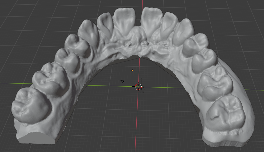
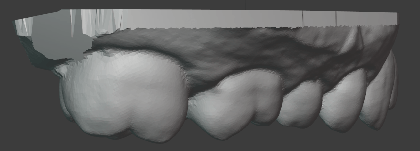
The 3D Scan
A digital model of the teeth is created from a 3D scan and then manipulated to create the sequence of models in the treatment. The scan needs to be accurate within the maximum step size so that the unmodified model is less than one step away from the teeth as they are. Then the second step may modify the teeth once they are in agreement with the 3D model of the first step. I did not have access to a professional 3D scanner, but I was able to pay someone with access to a NextEngine scanner to get what I could consider the ground truth further scanning attempts. Description of the attempt to replace the laser scan with photogrammetry makes more sense after understanding the remainder of the steps, so will come last.
Creating the Treatment Series
I will not comment on the core orthodontics of this because I am not an orthodontist. I will describe this from an engineering perspective because that is how I approached it.
Outside the domain knowledge of orthodontics, what can I deduce about how the orthodontic process works? What is the input information, and what is the output? The output is a series of 3D models of the maxilla or mandibula. If attachments are used, the algorithm should also produce those positions. The input information should be: an evaluation of dental health from visual inspection and dental records about past procedures, a 3D scan of the teeth, and an X-ray scan. The X-ray scan provides information about the positions of the roots of the teeth.
Suppose the teeth are perfectly rigid bodies, the mandibular and maxillary bones are rigid, and the connections between the two are like springs. The plastic aligners are semi-rigid bodies. When the arrangement of the teeth in the model differs from that of the real teeth, the model’s corresponding aligner produces a force on the teeth on the opposite side of the direction of movement. By Newton’s 3rd law, to produce such a force on a single tooth (suppose in the simplest case just a single tooth is targeted for movement) there must be an equal and opposite force distributed over other teeth. After being placed over the teeth, the aligner deforms and the teeth move such that the sum of the force vectors is zero. Critically, the deformation of the aligner (or of wire braces) cannot be ignored, and the resultant position of the teeth is not necessarily the same as the corresponding 3D model for that step.
Are there any restrictions on the movement possible? The aligner pushes against the teeth on the side opposite the direction of movement. For movement along the axis of each tooth (root to tip) there are not surfaces available in both directions, barring some concavity or irregularity on the surface of the tooth. The purpose of “attachments” is to make such surfaces available for axial movement.
So the aligner exerts forces on the target tooth and some of the other teeth such that the force vectors are balanced. The magnitude of these individual force vectors should be proportional to the difference between the real position of the teeth and the 3D model. What happens next? If I didn’t know anything about the physiology of the teeth, I would assume there is some adjustment in the connection between the teeth and the jaw that happens after every step. It turns out that the periodontic ligament is just that ‘spring’ connection, and that the bone surrounding the tooth will undergo harmless dissolution if a light force is applied against it, necrosis if a heavy force is applied, and the bone on the opposite side will grow to fill the cavity left. The goal is to exert a light force consistently to avoid this necrosis. Below some force magnitude, the surrounding bone will not undergo meaningful reshaping, which is why the opposite force vectors on the non-target teeth do not permanently move them. To apply this light force, the displacement of the teeth should be within some bounds. I have found values for this myself, but of course this is not something for which I am a proper source.
As anyone who has had orthodontic treatment knows, you can feel the magnitude of the force on your teeth. But don’t feel it ‘on’ the teeth themselves because there are no nerve endings on the exterior of the teeth. You only feel it in the living tissue inside of them and the ligament that connects them to the maxillary or mandibular bone. The physical sensation is a source of validation for the proper fabrication of the aligner. I can report for myself that the magnitudes of the forces applied in this sequence that I designed myself were much smaller than the feeling of the wire braces. When I had wire braces, it physically hurt to eat for a day after each adjustment, where here it was completely painless. For safety, I set the step size smaller than what I had found in the literature. It took longer and required more steps in the sequence, but the physical discomfort in the process was less and I could be (more) confident in the health of the process. With wire braces, if they are manually adjusted, you are simply putting your trust in the dexterity of the orthodontist to move them the correct amount, but with 3D printed positives, you have literal CNC control of the movement. I believe there are also automated wire bending tools now, so I’m not sure if this is a strictly superior method at least in this respect. I can’t speak to the relative accuracy and precision of such tools relative to the print and double-transfer process that I describe here.
I will refrain from going into the details of how exactly to determine the sequence for such a treatment. The thought of building a physics model to estimate the displacement of the teeth given some state and aligner shape crossed my mind, but I judged it to be unnecessary. My case was extremely simple, and I only learned what was necessary for it specifically. I’ll just say that it is more sophisticated than linear interpolation.
I did also have access to the X-ray scans of my mouth. Knowing about the physical positions of the roots of the teeth helps to determine the force system that the periodontic ligament exerts at any displaced position and the requisite change to the aligners. However, I don’t know if in name-brand treatments the X-ray scans are integrated with the 3D scans of the impressions of the teeth to compute the orthodontic sequence. I would think they would be very helpful, but I’m not sure. For the “teleorthodontic” treatments in which the client takes the impressions themselves, they of course do not have access to an X-ray scanner, so those treatment options go without integration of that information. In typical practice the orthodontist may simply use the X-ray scans for the evaluation of dental health. I did not do any sensor fusion either. I just used the scans as a reference to evaluate their health, estimate the spring force system, and be more confident that they would not collide with the movement I was planning,
Moving the teeth in Blender
Blender is free open-source software used for 3D modeling. It has a variety of uses in this project. When doing photogrammetry, it can be used to clean up the 3D scans. The major use is moving the teeth through the sequence of positions that are the sources for the 3D prints. To do this, I isolated the points of the mesh for each tooth that I wanted to move. Then, I manually determined each step and moved them at each iteration within the appropriate displacement value and within some boundary for angular change (again, it is more complicated than this).
Further benefits of a DIY treatment sequence
I had complete closed-loop control over the process. I was able to print as many steps of the sequence as I desired instead of printing the entire set and then doing a “readjustment” or realignment after a long series. If I made a mistake in any step, I could throw it out at negligible cost.
3D Printing
Preparing the Models for printing
Verify that the dimensions of the scan are correct by using the Measure tool in Blender.
Make a cut in the rear of the model so that there is an affordance for easily removing the print from the print bed.
Add an embossed number to each print for easy identification of each step in the sequence. Because the step sizes are so small, you may need to use calipers to distinguish them.
A print raft is not necessary because we don’t care about the bottom of the print.
Note the cut in the top left corner. This will make removing the print from the build plate much easier.
Printing
I bought an Elegoo Mars stereolithography (SLA, Resin-based) printer for this project. I had used fused-filament fabrication (FFF, extrusion-based) printers before, but the required resolution for this project would not have been possible with a consumer-grade printer. SLA printers are almost perfectly suited for this use case because they have impressive resolution (50 microns) and print in layers, which is aligned with the form factor of the prints (wide with low height). There are many great resources on Youtube for learning about 3D printing, and you could start with this video from 3D Print Farm.
Removing the print from the plate
I have not seen the following recommendations anywhere else. This process makes printing in batches much easier. In order to remove the print from the build plate without having to re-level the build plate after each print (which requires cleaning it to not risk any resin getting on the screen through the paper that is used for leveling) you should remove each print with these steps, which are somewhat specific to the Elegoo Mars printer:
Unscrew the large knob that holds the build plate fixture to the arm.
With the gloved non-dominant hand, grab the build plate by putting the thumb on one side and the other fingers on the opposite side across the narrow direction of the build plate.
Hold the build plate over a small container that will be used for rinsing the print.
With the included pallet knife in the dominant hand, insert the pallet knife in the notch in the print and twist the knife about the lengthwise axis (like turning a door knob). This creates a lever arm on the edge of the knife while having good control. Trying to use the pallet knife as a wedge by pushing in to the notch or turning it up does not work as well because the pallet knife is more flexible along that width-wise axis.
The print then drops into the cleaning container.
Return the build fixture to the build arm, and retighten the knob.
This means that at no point did you exert a force on the build plate and the knob segment at the same time, so their alignment hasn’t changed, and you don’t need to re-do the alignment of the build plate. I had first printed them without a notch, which made them difficult to remove because there was no affordance. I also tried to use the pallet knife as a wedge while the fixture was lying on the table, which changed the alignment of the build plate with the knob segment.
This allows for printing the steps in a sequence, cleaning them all together, and cleaning the printer once instead of for each print. Each of these prints took about 1hr 15min, so over the course of a day you can easily print 6+ of these. I found the process of cleaning the resin off of all the components tedious enough that consolidating the cleaning was very valuable.
Safety
It is important to understand that the resin is an irritant and you need to take the appropriate precautions when handling it. You need a well-ventilated room or garage. You need to follow the relevant rules for disposal of the uncured resin, especially for the cleaning supplies, because it is considered a hazardous material in its uncured form. There is more maintenance and cleaning required than an extrusion-based printer.
The reason that the resin printer is appropriate for this use case despite the additional required precautions is the resolution that it offers. In my experience, there is less adjustment and more confidence that the print will come out correctly on a resin printer than an extrusion printer. My one failed print happened when I pushed the build plate fixture out of alignment between prints without re-leveling it. Otherwise, the printing worked every time.
Cleaning
Some put emphasis on the cleaning solution for the resin print. I found that the most effective means of dislodging uncured resin was to directly brush the print with a tooth brush while it was in the cleaning solution. I did not see a difference in the results between the Mean Green Degreaser and Simple Green cleaning solution. Others use a hypersonic cleaning chamber. I did not find it to be necessary.
Curing the prints
In addition to cleaning the prints from remaining liquid resin, to ensure that the resin is fully cured, UV curing chambers are also used. I made my own from LED light strips of the appropriate wavelength in a box in which the interior sides were covered with aluminum foil and then the strips were overlaid. This gave a much larger volume than the of-the-shelf curing chambers I found, which allowed me to process them as a batch.
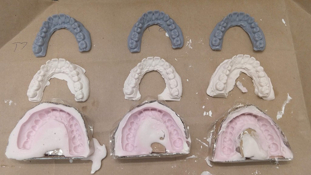
Duplication of the 3D prints to plaster casts
For the sake of safety, I chose to duplicate via double-transfer the 3D prints to plaster casts before vacuforming. First, I wanted to make sure that there would be no uncured resin transferred from the 3D print to the plastic aligner. Second, I did not know the thermal properties of the resin print. The plastic while doing vacuforming is made very hot, and I did not know if that had any chance of melting the print which would contaminate the plastic shell. To do this double-transfer, I made 3 jigs out of cardboard and packing tape in which I could do the alginate mold plus plastic cast. This was fairly straightforward. I was worried about a loss of precision and possible introduction of inaccuracy from each of these transformations, but this turned out not to be an issue.
The other reason why this may have been necessary (even if it turned out that there was no safety concern) was that it may have been too difficult to remove the vacuform from the 3D print, whereas with the plaster cast it can be destroyed in the process. I never successfully removed the vacuform from plaster cast without destroying the cast.
Vacuforming
To create the actual plastic aligner, we can heat a certain kind of plastic so that it becomes flexible, place it over the object around which it should be formed, and apply suction through the table on which the object is placed to suck out the air, which forms the plastic around the object. The casts around which we want to do the vacuform are small enough that the suction provided by a household vacuum cleaner is sufficient. To make the table, I made a box with holes drilled in one side and an opening for the vacuum cleaner hose in another. The region with holes was matched to the size of the plastic sheets that would be formed. To make the hole for the hose, I first traced the hose opening, cut out the same shape in cardboard, and then surrounded the hole with duct tape so that there would be a flexible seal around the hose as it was inserted. The other five faces of the box I made from MDF, which gave it rigidity.
For the heat source, I used a toaster oven that I got for this specific purpose instead of the kitchen oven as a precaution against any contamination of the kitchen oven with released fumes or particles. Also, the toaster oven was portable.
Then there needs to be a rigid frame to hold the plastic sheet while it is heated. I made a frame out of scrap aluminum by cutting four ~1″ x 6″ strips, making an incision on both narrow sides, and then making a bunny-ears wrap joint between each of the four strips to make a square. The key is that this frame should be thin so that there is not any unnecessary gap to the table, which could worsen draping effects. I then used eight “book darts” to hold the plastic sheet to the aluminum frame. Paper clips could also be used. Or, make one similar to a picture frame as shown in this video.
I then made stands attached to the toaster’s rack by taking aluminum foil, folding it over several times, and then shaping the strips into triangles with roughly the same height.
Vacuforming steps: Place the plaster cast on to the table, remove the plastic film if there is one from the plastic sheet, secure to the metal frame, insert the frame to the oven, heat the oven to ~325 deg F, wait until the plastic bends, turn on the vacuum, and then with thick gloves take the frame and lower it evenly onto the table. Wait for the plastic to cool so that it solidifies, turn off the vacuum. Detach plastic sheet from metal frame.
It might be possible to remove the the aligner from the plaster cast with just an x-acto knife, but it was easier to start with a small pair of scissors. Then remove burrs from the edge with the x-acto knife. Other sources call for a dremel with a special deburring tool, but I was able to get a clean edge with just an x-acto knife. Finally, wash the aligner thoroughly.
Professional-grade machines to do this are strangely expensive when it is just a heating element, vacuum source, table with holes, and tray. I suppose you can charge relatively high prices when your customers are high-margin businesses.
Wearing and Results
I took 3 weeks for each step, wearing the aligner except when eating. The obvious benefit of DIY (stated again) is that you can discard it and start over with low marginal cost if the magnitude of the change feels too large. I never had to do this, however. There may be some risk that wearing an aligner on only one set of teeth could affect the other set. I did not observe this.
Before:
After With Aligner:
After Without Aligner:
Photogrammetry
Photogrammetry is the process of obtaining physical measurements from photographs. Here I used a specific application of it: the creation of 3D models from a set of 2D images. My goal was to determine if I could get a 3D model of my teeth accurate enough to use as the basis for an orthodontic series. After reading the description of the entire fabrication process, you now have the context for the requirements of photogrammetry. Keep in mind that the 3D models will be printed and then their duplicates will be used as the positives for vacuforming. If a tooth is smaller in the model than the actual, the aligner will not fit over it. If it is larger, it will make exerting forces on it more difficult. If it is translated or rotated, the aligner will exert unexpected forces on the tooth.
As described above, I got the plaster cast of my teeth scanned using a NextEngine 3D laser scanner. This is a professional-grade machine, and it gave very impressive results. Orthodontists either take a scan from a plaster cast using a similar device, or from within the mouth itself with a specialized camera.
I had known about photogrammetry before this project, but this was my first attempt to use it. I had also considered building my own laser scanner or integrating a projector to do a structured light scan, but that would further increase the materials cost, and require very precise calibration to get right. With some searching I found these resources from Holocreators and Peter Falkingham on Small Object Photogrammetry, and decided to pursue photogrammetry with just my phone camera.
Similar to Peter Falkingham’s guide, I made a light box from a cardboard box, white LED light strips, and copy paper. I used a tripod to have my phone in a steady position relative to the box and a remote clicker so that I wouldn’t need to disturb the phone by touching it, which would cause blur.
From there, I used the open source Meshroom/AliceVision software to process the set of images into a 3D model. This requires an NVIDIA GPU. If you don’t have one you could use the Google Colab free tier to process the images. This notebook provides an example.
The mesh output from Meshroom can be cleaned up and examined in Blender. Note that you will need to scale the output from Meshroom by taking real measurements on the cast and then scaling the model such that the distance for the measurement of the equivalent points is the same.
Because the plaster cast is uniformly white, it does not offer good visual features for the automated extraction of keypoints by the photogrammetry software. Here it helps to have some understanding of the underlying process. The first step is to extract visual keypoints which, loosely speaking, are visually striking and distinct points on an object that should be apparent at different angles and distances, and when collected together can be used to identify an object and the angle at which it is observed. These are things like edges, corners, regions of high-frequency color changes, etc. Once these visual features are extracted from every image, their positions within each image can be compared to determine the camera position and angle that corresponds to each image. In turn, this allows for finer estimation of the distance from each camera angle to every pixel in its image. Read more at AliceVision’s guide.
The unmodified plaster cast has relatively few such keypoints, and to add more, I painted the cast using acrylic paints to create a high density of color changes and edges. I had first tried just using pencil, pens, and markers, but painting in small strokes and dabs with partially blended colors on the brush offered much better visual feature density. This was a very low cost modification to the physical object which greatly improved the scanning performance. Laser or structured light scanners operate on a similar principle of creating visual features, but instead project some pattern or point onto the object and then record the resulting deformation of the projection to make measurements.
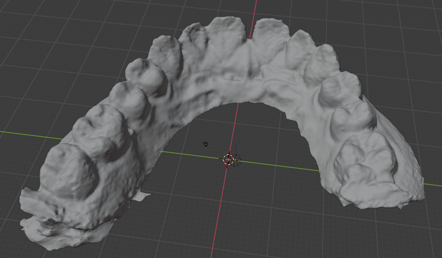
The result of the photogrammetry was accurate to the laser scan within ~0.6 mm almost everywhere, which was impressive for just a phone camera and open source software, but not quite good enough for unmodified use as the basis for an orthodontic sequence. There is certainly much more that I could have tried. Perhaps I could have gotten better results by experimenting with the Meshroom settings.
I manually configured the camera focus and exposure time to get high resolution and contrast. The automatic setting of the other features seemed to be good enough. One problem I encountered that may be somewhat specific to this use case was that it was difficult to get a consistent level of focus on both halves of the teeth. The photogrammetry examples I have seen have been on objects that are mostly convex. Here I attempted to take close-up photos with high resolution in which the ratio of distances between the camera and the different parts of the object was significant.
Note that the left rear molar is missing because I used an incomplete fragment for my photogrammetry testing. The above image shows the raw result. It could be cleaned up in Blender with smoothing, refining some of the edges, etc.
My result was not even in the same class as Peter Falkingham’s for what I assume are objects of similar size, but he also had a DSLR camera.
To compare the photogrammetry result with the laser scan I used CloudCompare. See these tutorials:
Despite the insufficient accuracy, I think it would still be possible to use only the photogrammetry techniques described so far if you use a somewhat tedious error correcting process. After validating that it looks correct visually (no major defects or deformations) and checking with the measurement tool in Blender, you can do a few things:
Print it, do the vacuum forming, cut it out, and try to fit the plastic shell over the original cast. The shell is somewhat flexible, so it should be possible to fit it over the cast if it is close, and you can hopefully observe the areas where the fit is not correct, and then make adjustments in Blender. Obviously, the better the scan, the fewer adjustments need to be made. Flexibility means that it should be possible to fit it over the shell despite concavities.
Because the cast is rigid and your teeth actually move slightly, it may be more difficult to fit the shell over the cast than over your teeth. Given that the goal is to eventually fit it over your teeth, you can just try to put the shell over your teeth and then literally feel the regions where the fit is not right. If it can’t actually fit, you need major adjustments, and then you can feel if there needs to be a move and in what direction from the force on your gums. Of course, it is important to not try to force it. Again, I have not tried to do this.
Doing the corrections would take some skill in Blender.
The goal for the variance of the scan should be less than the recommended step size. A scan within that variance would be equivalent to one step size which should be just barely perceptible. Instead of starting with the first “treatment” tray, start with the product of the unmodified scan so that there is agreement between the scan’s starting place and the sequence of the treatment.
I also was aware of newer neural network-based approaches to constructing 3D models such as Neural Radiance Fields but the convergence times for these were quite long. Iteration speed was important in trying to construct the photo set and analyzing how to improve it, so I decided to go with the more established tools for this investigation. I expect that within a few years these newer approaches will become more efficient and mature for this use case.
The photogrammetry process is quite tedious compared to the cost of having it done with a laser scanner. If you would enjoy learning this skill, go for it, otherwise, it is probably simpler to find someone with access to a scanner (perhaps a university student or someone in a maker space) who could do this for you. Unless you want to track your progress very precisely, you would only need a single scan. This is the only part of the process for which consumer-grade equipment is not sufficient.
Conclusion
Overall, this project was more like acquiring a time-intensive hobby that eventually saved money than what one might think of as a DIY solution. Again, this is not orthodontic advice. I am not encouraging you to do this. My case was extremely simple.
Bill of Materials
The total cost when I purchased these materials was about $430. Availability or cost may have changed since then. Of the purchased materials, the cost of durable goods was about $310 (mostly the 3D printer), and the unit cost of consumables was approximately $60. I paid $100 to have the laser scan done.